Publication 1762-UM001D-EN-P - March 2004
3-22 Wiring Your Controller
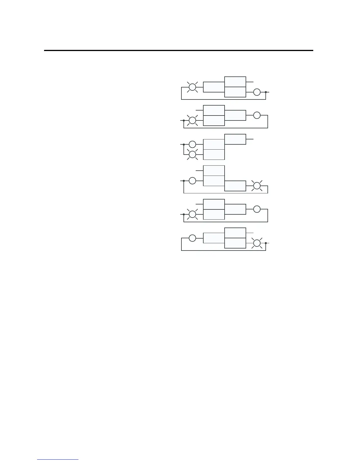
Figure 3.29 1762-OX6I Wiring Diagram
Analog Wiring
System Wiring Guidelines
Consider the following when wiring your analog modules:
• The analog common (COM) is not connected to earth ground
inside the module. All terminals are electrically isolated from the
system.
• Channels are not isolated from each other.
• Use Belden™ 8761, or equivalent, shielded wire.
• Under normal conditions, the drain wire (shield) should be
connected to the metal mounting panel (earth ground). Keep
the shield connection to earth ground as short as possible.
L1-0
L1-1
L1-2
L1-3
L1-4
L1-5
OUT0 N.C.
OUT0 N.O.
OUT1 N.C.
OUT1 N.O.
OUT2 N.C.
OUT2 N.O.
OUT3 N.O.
OUT3 N.C.
OUT4 N.C.
OUT4 N.O.
OUT5 N.C.
OUT5 N.O.
CR
CR
CR
CR
CR
CR
L1 OR +DC
L1 OR +DC
L1 OR +DC
L1 OR +DC
L1 OR +DC
L1 OR +DC
L2 OR -DC
L2 OR -DC
L2 OR -DC
L2 OR -DC
L2 OR -DC
L2 OR -DC

 Loading...


