Publication 1762-UM001D-EN-P - March 2004
System Loading and Heat Dissipation F-7
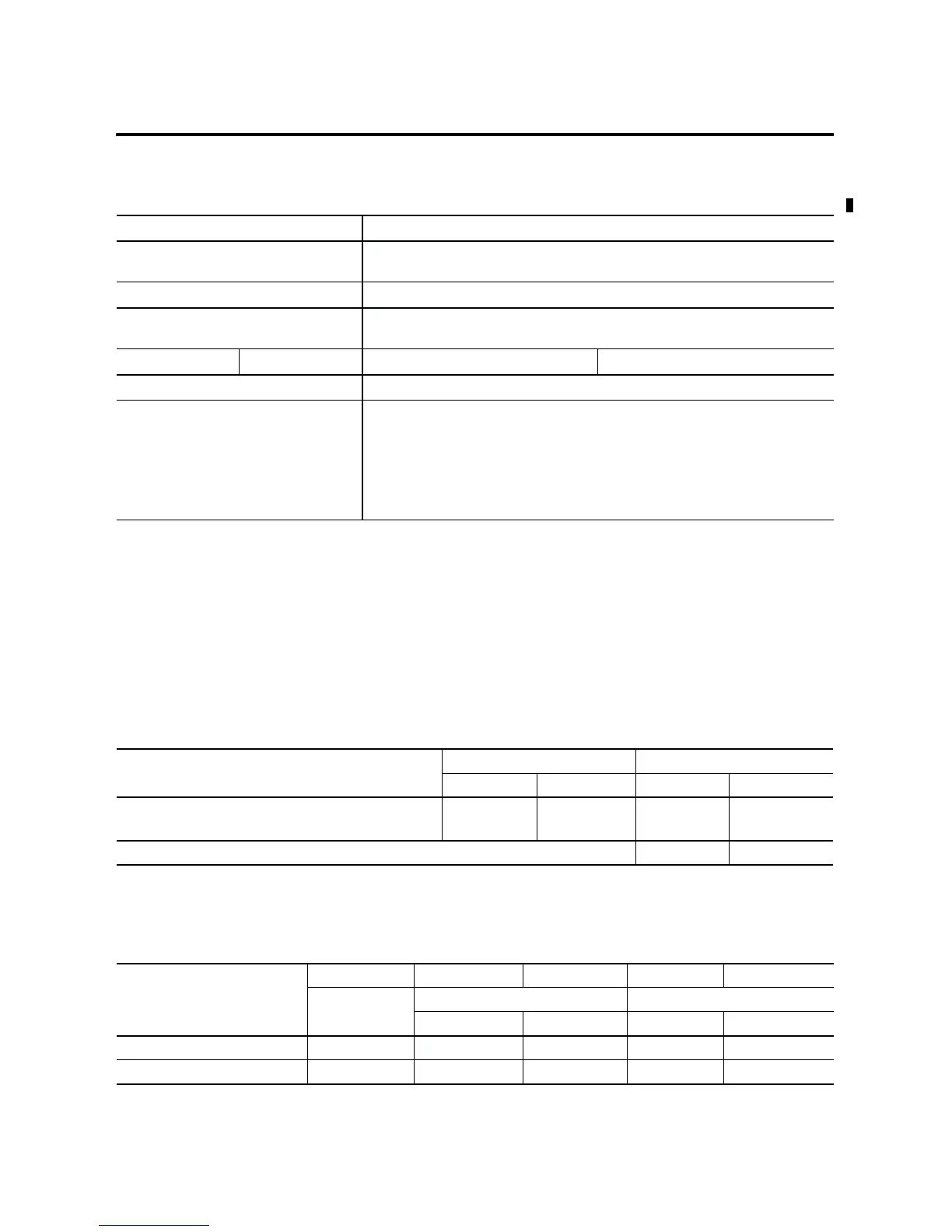
System Loading Worksheet
The tables below are provided for system loading validation for
40-Point Controllers. See System Loading Example Calculations
(40-Point Controller) on page F-5.
Current Loading
Table F.12 Validating Systems using 1762-L40BWA or 1762-L40BWAR
Maximum Allowable Values Calculated Values
Current for Devices Connected to the +24V dc
Sensor Supply:
Sum of all current sensors
400 mA at 24V dc 150 mA at 24V dc (example sensor value)
Current for MicroLogix Accessories and
Expansion I/O:
Current (Subtotal 1 from Table F.9 + Subtotal 2 from Table F.10):
600 mA at 5V dc 500 mA at 24V dc 0 mA + 395 mA = 395 mA at 5V dc 120 mA + 245 mA = 365 mA at 24V dc
System Loading: System Loading:
16 Watts
= (150 mA x 24V) + (395 mA x 5V) + (365 mA x 24V)
= (3600 mW) + (1975 mW) + (8760 mW)
= 14335 W
= 14.34 Watts
Table F.13 Calculating the Current for MicroLogix Accessories
Catalog Number Device Current Requirements Calculated Current
at 5V dc (mA) at 24V dc (mA) at 5V dc (mA) at 24V dc (mA)
1761-NET-AIC
(1)
when powered by the base unit
communications port, selector switch in the up position
0120
Subtotal 1:
(1) This is an optional accessory. Current is consumed only if the accessory is installed.
Table F.14 Calculating the Current for Expansion I/O
Catalog Number
(1)
n A B n x A n x B
Number of
Modules
Device Current Requirements Calculated Current
at 5V dc (mA) at 24V dc (mA) at 5V dc (mA) at 24V dc (mA)
1762-IA8 50 0
1762-IQ8 50 0

 Loading...


