Publication 1762-UM001D-EN-P - March 2004
F-6 System Loading and Heat Dissipation
Validating the System
The example systems shown in Table F.11 and Table F.12 are verified
to be acceptable configurations. The systems are valid because:
• Calculated Current Values < Maximum Allowable Current
Values
• Calculated System Loading < Maximum Allowable System
Loading
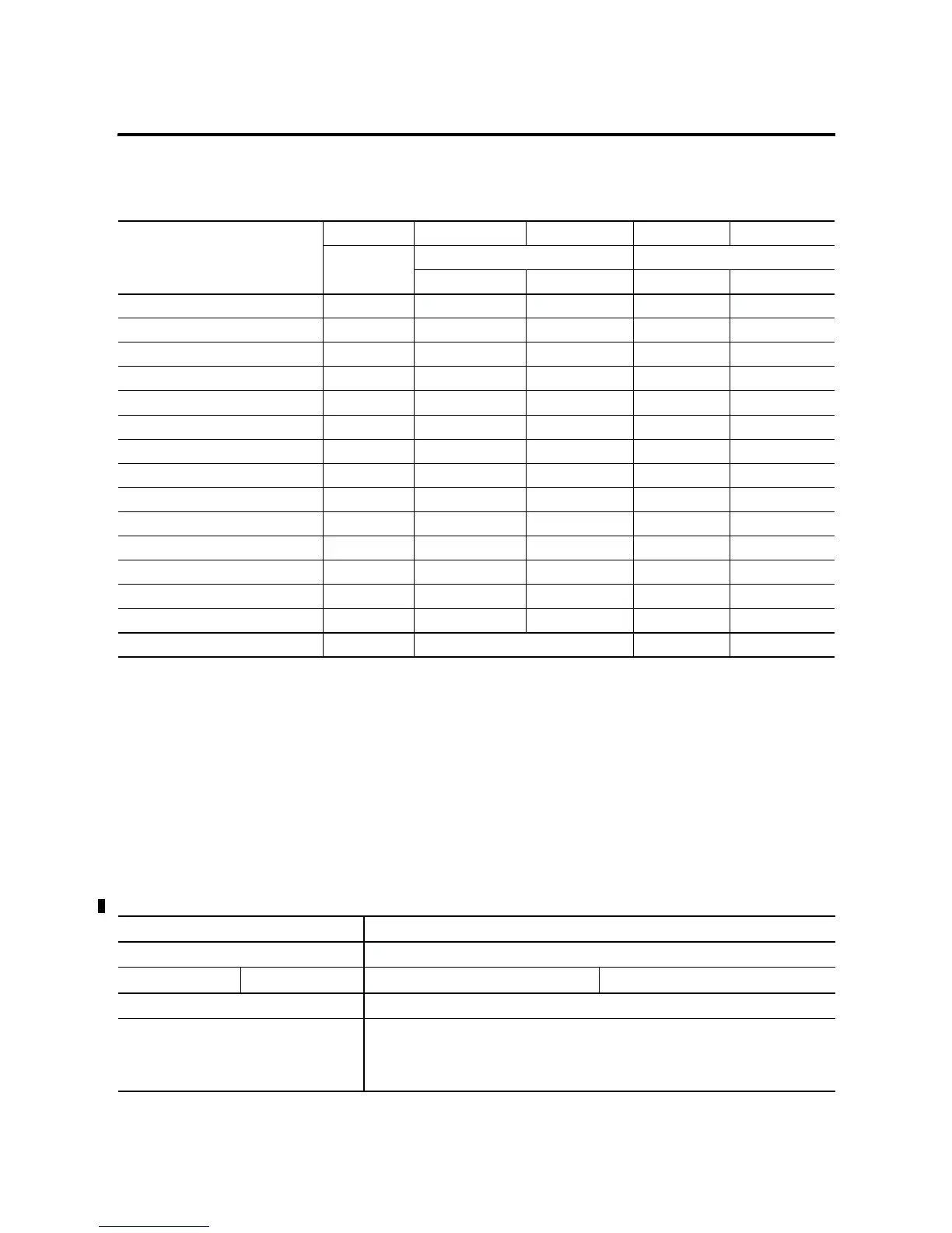
Table F.10 Calculating the Current for Expansion I/O
Catalog Number
(1)
n A B n x A n x B
Number of
Modules
Device Current Requirements (max) Calculated Current
at 5V dc (mA) at 24V dc (mA) at 5V dc (mA) at 24V dc (mA)
1762-IA8 50 0
1762-IF4 40 50
1762-IF2OF2 1 40 105 40 105
1762-IQ8 50 0
1762-IQ16 2 60 0 120 0
1762-IR4 40 50
1762-IT4 40 50
1762-OA8 1 115 0 115 0
1762-OB8 115 0
1762-OB16 175 0
1762-OF4 40 165
1762-OW8 80 90
1762-OW16 1 120 140 120 140
1762-OX6I 110 110
Total Modules (6 maximum): 6 Subtotal 2: 395 245
(1) Refer to your expansion I/O Installation Instructions for Current Requirements not listed in this table.
Table F.11 Validating Systems using 1762-L40AWA, 1762-L40BXB, 1762-L40AWAR or 1762-L40BXBR
Maximum Allowable Values Calculated Values
Current: Current (Subtotal 1 from Table F.9 + Subtotal 2 from Table F.10):
600 mA at 5V dc 500 mA at 24V dc 0 mA + 395 mA = 395 mA at 5V dc 120 mA + 245 mA = 365 mA at 24V dc
System Loading: System Loading:
15 Watts
= (395 mA x 5V) + (365 mA x 24V)
= (1975 mW) + (8760 mW)
= 10,735 mW
= 10.74 Watts

 Loading...


