Publication 1762-UM001D-EN-P - March 2004
Communication Connections 4-17
Safety Considerations
This equipment is suitable for use in Class I, Division 2, Groups A, B,
C, D or non-hazardous locations only.
See Safety Considerations on page 2-3 for additional information.
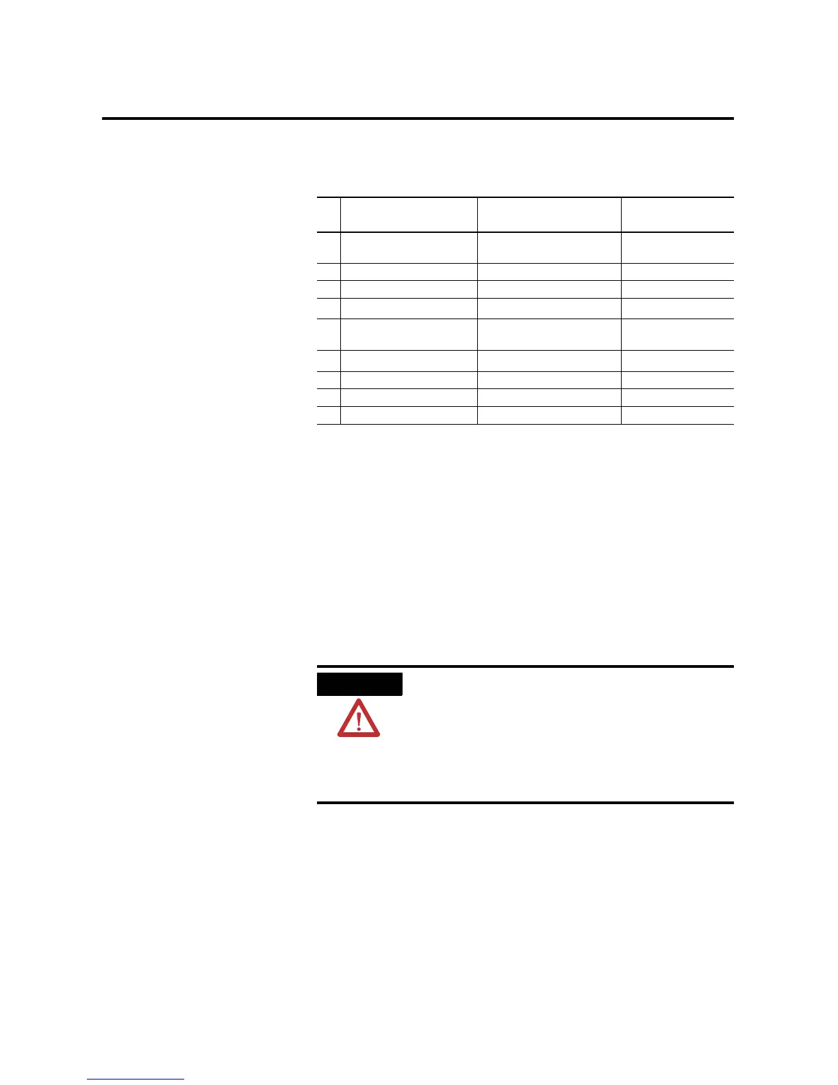
Table 4.7 AIC+ Terminals
Pin Port 1: DB-9 RS-232
Port 2
(2)
: (1761-CBL-PM02
cable)
(2)
An 8-pin mini DIN connector is used for making connections to port 2. This connector is not commercially
available. If you are making a cable to connect to port 2, you must configure your cable to connect to the
Allen-Bradley cable shown above.
Port 3: RS-485
Connector
1 received line signal detector
(DCD)
24V dc chassis ground
2 received data (RxD) ground (GND) cable shield
3 transmitted data (TxD) request to send (RTS) signal ground
4
DTE ready (DTR)
(1)
(1)
On port 1, pin 4 is electronically jumpered to pin 6. Whenever the AIC+ is powered on, pin 4 will match the
state of pin 6.
received data (RxD)
(3)
(3)
In the 1761-CBL-PM02 cable, pins 4 and 6 are jumpered together within the DB-9 connector.
DH-485 data B
5 signal common (GND) received line signal detector
(DCD)
DH-485 data A
6
DCE ready (DSR)
(1)
clear to send (CTS)
(3)
termination
7 request to send (RTS) transmitted data (TxD) not applicable
8 clear to send (CTS) ground (GND) not applicable
9 not applicable not applicable not applicable
WARNING
EXPLOSION HAZARD
AIC+ must be operated from an external power
source.
This product must be installed in an enclosure. All
cables connected to the product must remain in the
enclosure or be protected by conduit or other
means.

 Loading...


