Publication 1762-UM001D-EN-P - March 2004
System Loading and Heat Dissipation F-3
System Loading Worksheet
The tables below are provided for system loading validation for
24-Point Controllers. See System Loading Example Calculations
(24-Point Controller) on page F-1.
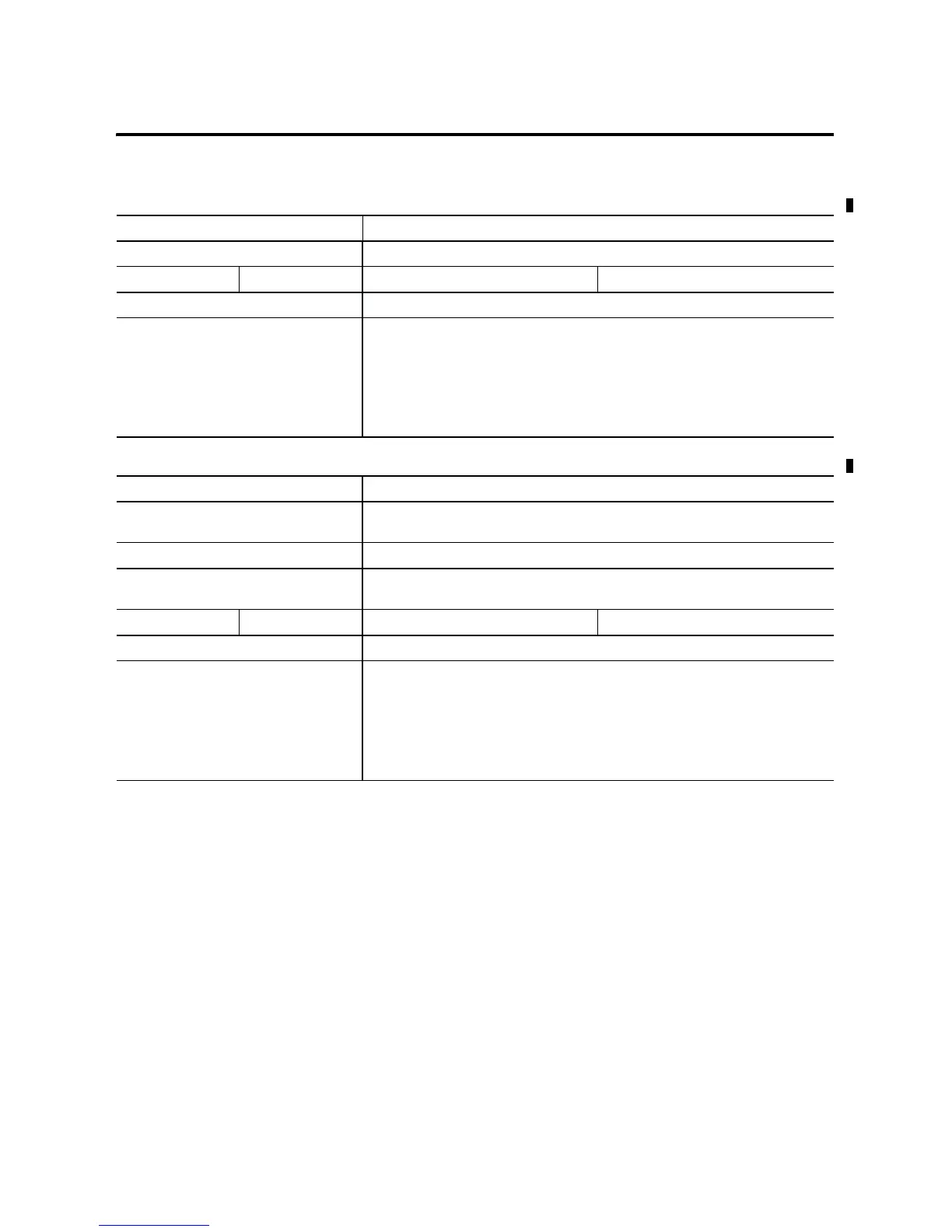
Table F.3 Validating Systems Using 1762-L24AWA, 1762-L24BXB, 1762-L24AWAR or 1762-L24BXBR
Maximum Allowable Values Calculated Values
Current: Current (Subtotal 1 + Subtotal 2 from Table F.1 and Table F.2 on page F-2.):
400 mA at 5V dc 350 mA at 24V dc 0 mA + 260 mA = 260 mA at 5V dc 120 mA + 180 mA = 300 mA at 24V dc
System Loading: System Loading:
10.4 Watts
= (260 mA x 5V) + (300 mA x 24V)
= (1300 mW) + (7200 mW)
= 8500 mW
= 8.50 Watts
Table F.4 Validating Systems using 1762-L24BWA or 1762-L24BWAR
Maximum Allowable Values Calculated Values
Current for Devices Connected to the +24V dc
Sensor Supply:
Sum of all sensor currents
250 mA at 24V dc 140 mA at 24V dc (example sensor value)
Current for MicroLogix Accessories and
Expansion I/O:
Current Values (Subtotal 1 from Table F.1 + Subtotal 2 from Table F.2):
400 mA at 5V dc 350 mA at 24V dc 0 mA + 260 mA = 260 mA at 5V dc 120 mA + 180 mA = 300 mA at 24V dc
System Loading: System Loading:
12 Watts
= (140 mA x 24V) + (260 mA x 5V) + (300 mA x 24V)
= (3360 mW) + (1300 mW) + (7200 mW)
= 11,860 mW
= 11.9 Watts

 Loading...


