1 Publication 1762-UM001D-EN-P - March 2004
Chapter
5
Using Trim Pots
Trim Pot Operation
The processor has two trimming potentiometers (trim pots) which
allow modification of data within the controller. Adjustments to the
trim pots change the value in the corresponding Trim Pot Information
(TPI) register. The data value of each trim pot can be used throughout
the control program as timer, counter, or analog presets depending
upon the requirements of the application.
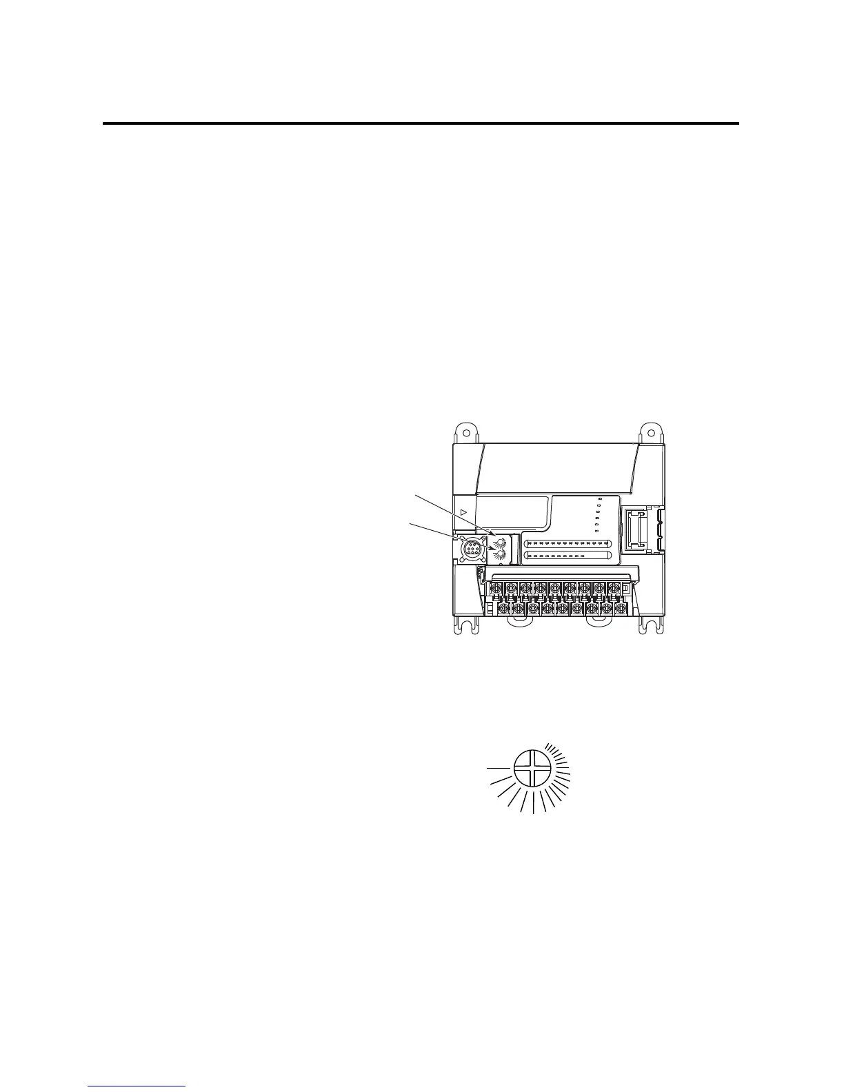
The trim pots are located below the memory module port cover and
to the right of the communications port, as shown below.
Use a small flathead screwdriver to turn the trim pots. Adjusting their
value causes data to change within a range of 0 to 250 (fully
clockwise). The maximum rotation of each trim pot is three-quarters,
as shown below. Trim pot stability over time and temperature is
typically ±2 counts.
Trim pot file data is updated continuously whenever the controller is
powered-up.
0
1
COM
Trim Pot 0
Trim Pot 1
Maximum
Minimum

 Loading...


