Publication 1762-UM001D-EN-P - March 2004
Installing Your Controller 2-19
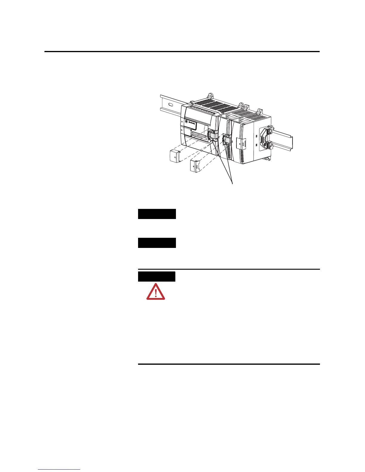
Connecting Expansion I/O
The expansion I/O module is attached to the controller or another I/O
module by means of a flat ribbon cable after mounting, as shown
below.
TIP
Use the pull loop on the connector to disconnect
modules. Do not pull on the ribbon cable.
TIP
Up to six expansion I/O modules can be connected
to a controller depending upon the power supply
loading.
ATTENTION
Remove power before removing or inserting an I/O
module. When you remove or insert a module with
power applied, an electrical arc may occur. An
electrical arc can cause personal injury or property
damage by:
• sending an erroneous signal to your system’s field
devices, causing the controller to fault
• causing an explosion in a hazardous environment
Electrical arcing causes excessive wear to contacts on
both the module and its mating connector. Worn
contacts may create electrical resistance, reducing
product reliability.
Pull Loop

 Loading...


