218 Rockwell Automation Publication 1783-UM007G-EN-P - February 2017
Chapter 7 Configure Switch Features
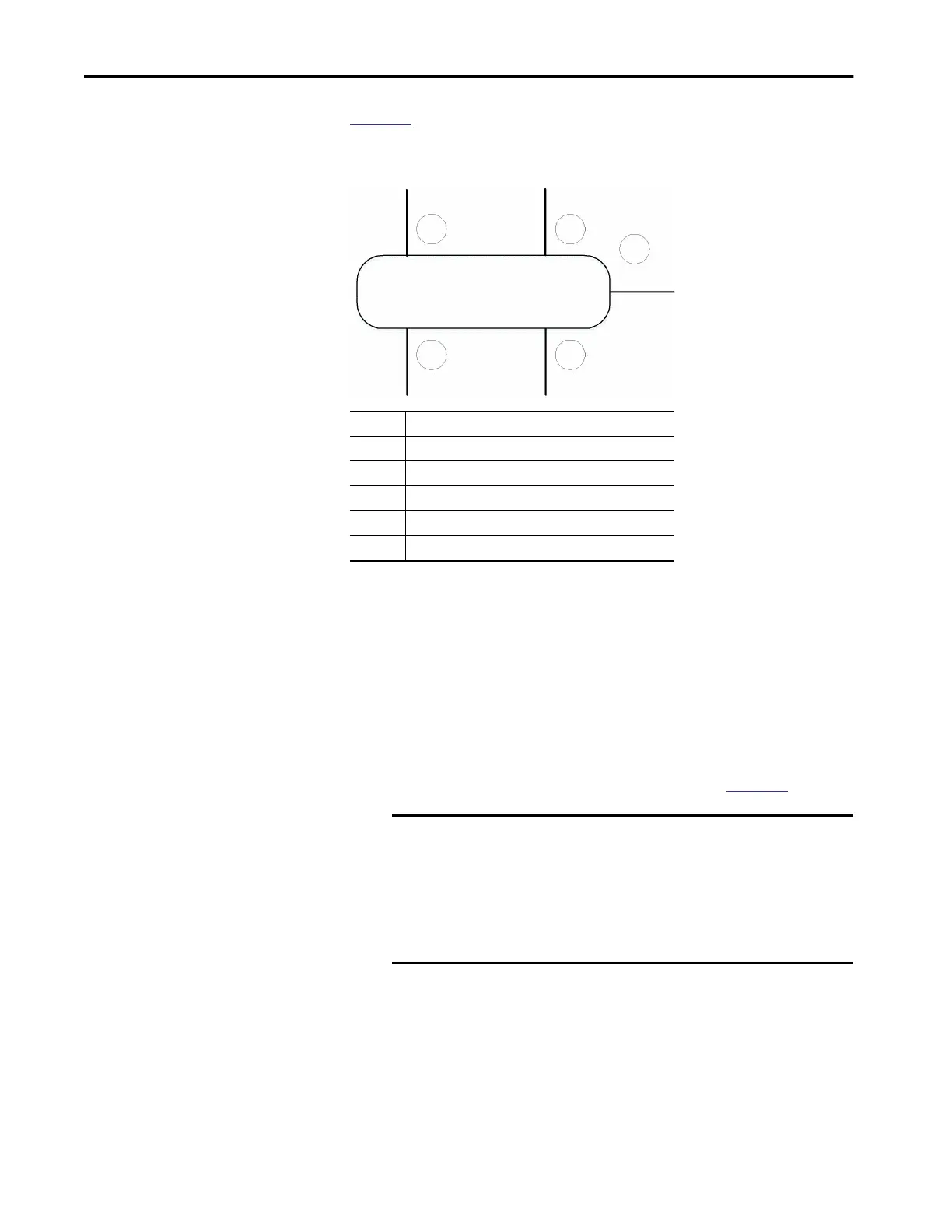
Figure 14 shows an example of a switch configured for redundant gateway. All
ports are assigned to VLAN 1.
Figure 14 - Redundant Gateway Switch Ports
When the switch acts as the active redundant gateway, traffic on the switch
that is assigned to VLAN 1 can flow between ports A, B, C, D, and E.
When the switch acts a backup redundant gateway, traffic on the switch that is
assigned to VLAN 1 can flow as follows:
• Between only Ports A and B
• Between only Ports C, D, and E
• To join the ring, traffic on Ports C, D, and E must flow through the non-
DLR port, through devices connected to the backup redundant gateway,
and then through the active redundant gateway (see
Figure 15).
• If the backup gateway subsequently becomes the active gateway, traffic
then begins to flow between all ports.
Port Configuration
A DLR access port
B DLR access port
C Redundant gateway uplink port
D Redundant gateway uplink port
E Non-DLR port
IMPORTANT Traffic flow restrictions from the backup gateway to the ring include
CIP and Device Manager traffic. As a result, all traffic flowing from a
ring device to the backup gateway must use this path:
• Exit the ring through the active gateway
• Flow through the outside network above the ring
• Enter the backup gateway through the uplink port.
C
AB
D
E
 Loading...


