Publication 2098-IN003E-EN-P — April 2004
Interconnect Diagrams B-5
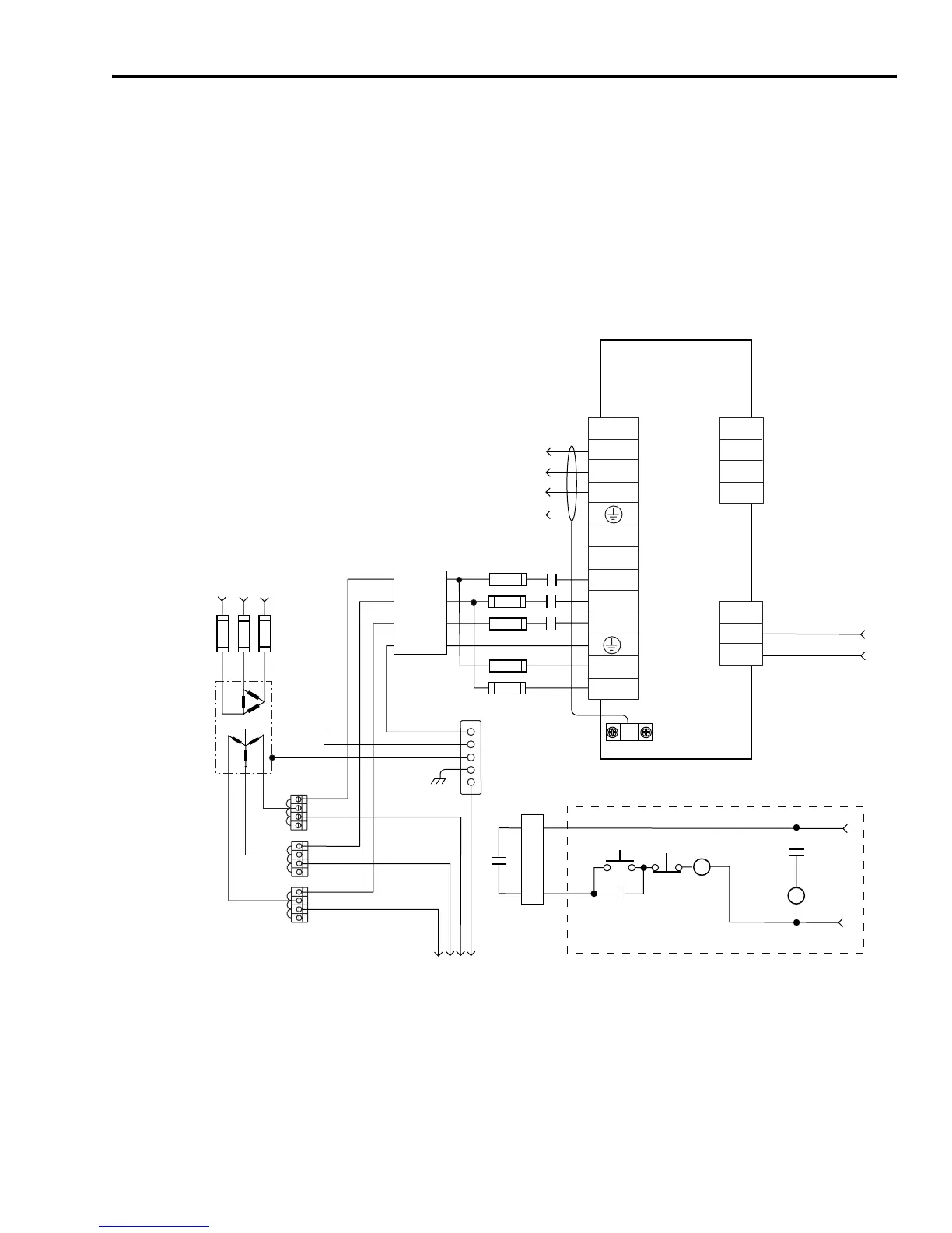
The Ultra3000 (2098-DSD-075x-xx and -150x-xx) power wiring with
24V dc control string (non-SERCOS drives only) is shown in the figure
below. For the control string diagram with 120V ac input refer to
Figure B.18.
For SERCOS drives, input line contactor is part of the PLC program
and output control.
Figure B.3
Typical Power Wiring of Ultra3000 System
(2098-DSD-075x-xx and -150x-xx)
Note: Refer to Figure 2.26 in the chapter Ultra3000 Connector Data
for more information on the relay output.
TB1
U
V
W
DC+
DC-
L1
L2
L3
L1 AUX
L2/N AUX
L2
L1
CN1
43
44
L3
TB2
1
2
3
43
44
CN1
43
44
Ultra3000
Digital Servo Drives
2098-DSD-075x-xx and
-150x-xx
Note 13
AC Input Power
Connections
Motor Power
Connections
Three-Phase
AC Line Filter
Note 7
Input Fusing*
Note 4, 5
Three-Phase Input
100-240V ac RMS
Fused Disconnect
or Circuit Breaker*
Note 1
Isolation
Transformer*
Note 2
Chassis
Bonded Cabinet
Ground Bus*
Terminal
Blocks*
Note 3
To additional
Ultra3000 drive
Three-Phase
Motor Power
Connections
Note 12
Cable Shield
Clamp
Note 9
* INDICATES USER-SUPPLIED COMPONENT
STOP*
START*
CR1*
CR1*
CR1*
M1*
Refer to Attention statement (Notes 10, 11)
N.O. Relay Output+
N.O. Relay Output-
Note 20
24V dc
Neutral
Note 6
M1*
Note 8
External Passive
Shunt Connections
(refer to figures
beginning on B-7)
Three-Phase AC Line
50/60 Hz
 Loading...


