Publication 2098-IN003E-EN-P — April 2004
B-8 Interconnect Diagrams
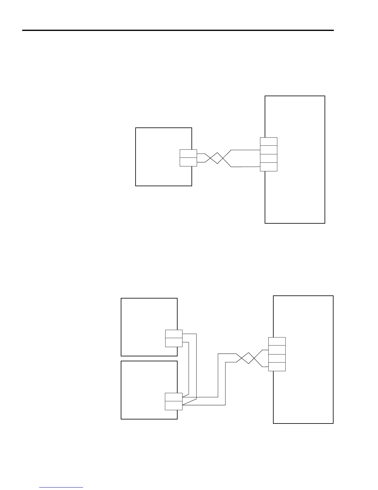
In the figure below, the Ultra3000 is shown wired with an external
passive shunt resistor. Refer to External Shunt Kits in Appendix C for
Ultra3000/shunt combinations.
Figure B.7
External Passive Shunt Module Interconnect Diagram
In the figure below, the Ultra3000 (2098-DSD-150x-xx) is shown wired
with two external passive shunt resistors. When two 900W shunt
modules are connected in parallel, the shunt capacity is doubled for a
total of 1800W of continuous power dissipation.
Figure B.8
External Passive Shunt Module Interconnect Diagram
TB2
1
2
3
Ultra3000
Digital Servo Drives
2098-DSD-030x-xx,
-075x-xx, -150x-xx,
-HVxxx-xx, and
-HVxxxX-xx
External Passive Shunt
Resistor Connections
External Passive
Shunt Module
DC+
COL
TB2
1
2
3
Ultra3000
Digital Servo Drives
2098-DSD-150x-xx
External Passive Shunt
Resistor Connections
External Passive
Shunt Module
2090-UCSR-P900
External Passive
Shunt Module
2090-UCSR-P900
DC+
COL
DC+
COL
 Loading...


