Publication 2098-IN003E-EN-P — April 2004
Interconnect Diagrams B-9
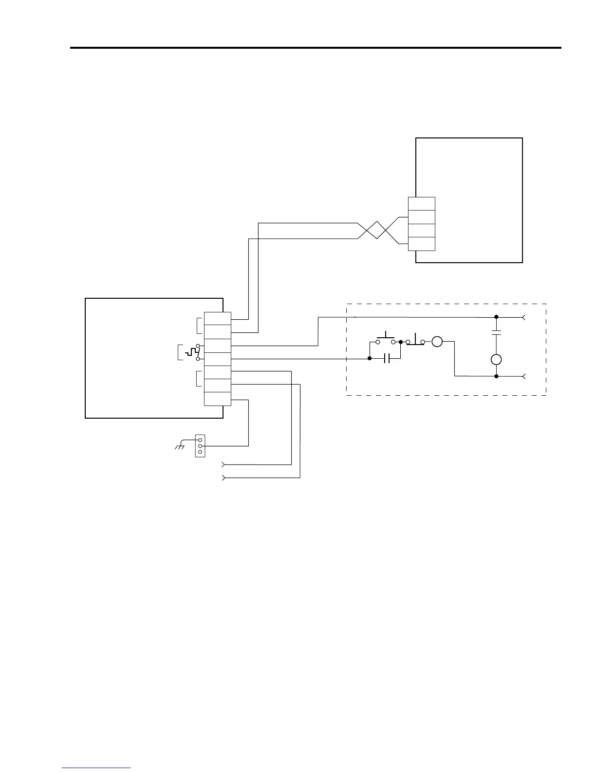
In the figure below, the Ultra3000 (2098-DSD-HV150x-xx or
-HV220x-xx) is shown wired to a Bonitron shunt module.
Figure B.9
External Passive Shunt Module Interconnect Diagram
TB2
1
2
3
GRN
115VAC
Fan
RES
TEMP
Alarm
1
2
3
4
5
6
7
External Passive Shunt
Resistor Connections
Bonitron
Shunt Module *
M3575R-Hxxxx
Ultra3000
Digital Servo Drives
2098-DSD-HV150x-xx
or
2098-DSD-HV220x-xx
Bonded Cabinet
Ground Bus*
115V ac
Fan Power*
STOP*
START*
CR1*
CR1*
CR1*
M1*
Refer to Attention statement (Notes 10, 11)
120V ac
50/60 Hz
* INDICATES USER-SUPPLIED COMPONENT
Shunt Wiring Methods:
Twisted pair in conduit (1st choice).
Shielded twisted pair (2nd choice).
Twisted pair, 2 twists per foot min. (3rd choice).
Maximum Length: 3.05 m (10 ft).
 Loading...


