Publication 2098-IN003E-EN-P — April 2004
2-8 Ultra3000 Connector Data
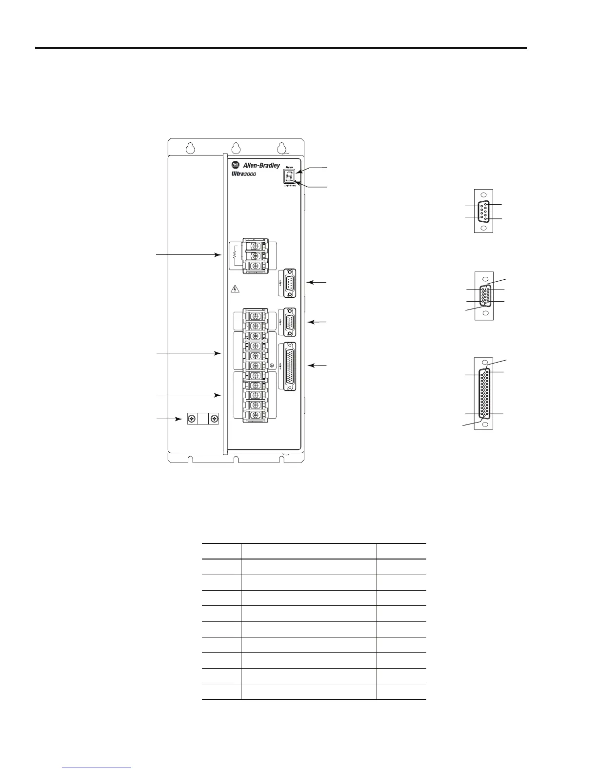
Use the figure below to locate the front panel connections on the
Ultra3000 460V drives (3W, 5 kW, 10 kW, 15 kW, and 22 kW).
Figure 2.4
Ultra3000 Front Panel Connections for 2098-DSD-HVxxx and HVxxxX
Serial Port Connector
The following table provides the signal descriptions and pin-outs for
the CN3 serial port (9-pin) connector.
W
V
U
+
-
L3
L2
L1
L1
AUX
L2
AUX
Motor
DC Bus
230-480 VAC
50/60 Hz
Internal
External Shunt
1
2
3
TB2
REGNAD REGNAD
Hazardous voltage
exists after power down.
TB1
Pin 11
Pin 6
Pin 15
Pin 1
Pin 10
Pin 5
Pin 30
Pin 44
Pin 1
Pin 15
Pin 16
Pin 31
Pin 6
Pin 9
Pin 1
Pin 5
AC Input Power
Connections
Motor Power
Connections
Passive Shunt
Resistor Connections
Seven Segment
Status LED
Logic Power LED
CN3 9-pin
Serial Port
Connector
CN2 15-pin
Motor Feedback
Connector
CN1 44-pin
User I/O
Connector
Motor Power
Cable Shield Clamp
9-pin CN3
Serial Connector
15-pin CN2
Feedback Connector
44-pin CN1
I/O Connector
CN3 Pin Description Signal
1 RS-422/RS-485 Input+ RCV+
2 RS-232 Input RCV
3 RS-232 Output XMT
4 RS-422/RS-485 Output+ XMT+
5 Common COM
6 Reserved –
7 RS-422/RS-485 Input- RCV-
8 RS-422/RS-485 Output- XMT-
9 Reserved –

 Loading...


