6–64 Copyright © 1998 General Motors Corp.
WTEC II ELECTRONIC CONTROLS TROUBLESHOOTING MANUAL
PROBING THE CONNECTOR
When testing the control system from the feedthrough connector with the internal harness connected, contact with
the following pairs of terminals will result in resistance measurements of two solenoids through a shared ground.
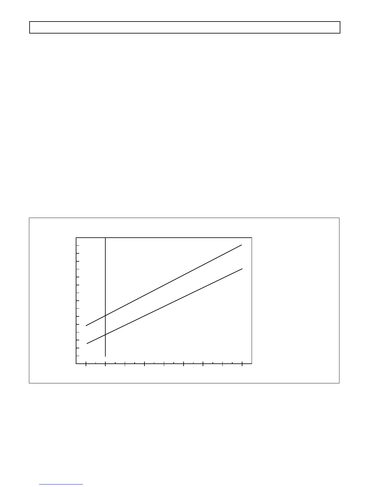
The resistance should be twice that of a single solenoid. Refer to Figure 6–23 for solenoid resistance values versus
temperature.
NOTE: Before troubleshooting, read Pages 6–17 and 6–18 of Section 6–5. Also, check battery and ECU input
voltages.
NOTE: The retarder accumulator solenoid (“H”) has a 30 Ohm coil. Since “H” solenoid is not mounted in
the sump, no relationship between temperature and resistance is required.
Figure 6–23. Solenoid Resistance vs. Temperature
Terminals
Solenoids Which
Share Ground
A1, D1 A, D
B1, E1 B, E
C1, F1 C, G
V00719.01
MAXIMUM OHMS
WT SOLENOID RESISTANCE
SPEC VALUE=3.26±.2 OHMS AT 20°C
MINIMUM OHMS
SOLENOID RESISTANCE IN OHMS
4.8
5.2
4.6
5
4.4
4.2
4
3.8
3.6
3.4
3.2
3
2.8
2.6
2.4
2.2
2
-20 0 20 40 60 80 100 120 140
4 32 68 104 140 176 212 248 284
SUMP TEMPERATURE IN °F
SUMP TEMPERATURE IN °C
CODE 41 XX — OPEN OR SHORT-TO-GROUND IN SOLENOID CIRCUIT
(Figures 6–21, 6–22)