WTEC II ELECTRONIC CONTROLS TROUBLESHOOTING MANUAL
P–20 Copyright © 1998 General Motors Corp.
APPENDIX P — INPUT/OUTPUT FUNCTIONS
WARNING!
These schematics show the intended use of the specified controls features which
have been validated in the configuration shown. Any miswiring or use of these
features which differs from that shown could result in damage to equipment or
property, personal injury, or loss of life. ALLISON TRANSMISSION IS NOT
LIABLE FOR THE CONSEQUENCES ASSOCIATED WITH MISWIRING
OR UNINTENDED USE OF THESE FEATURES.
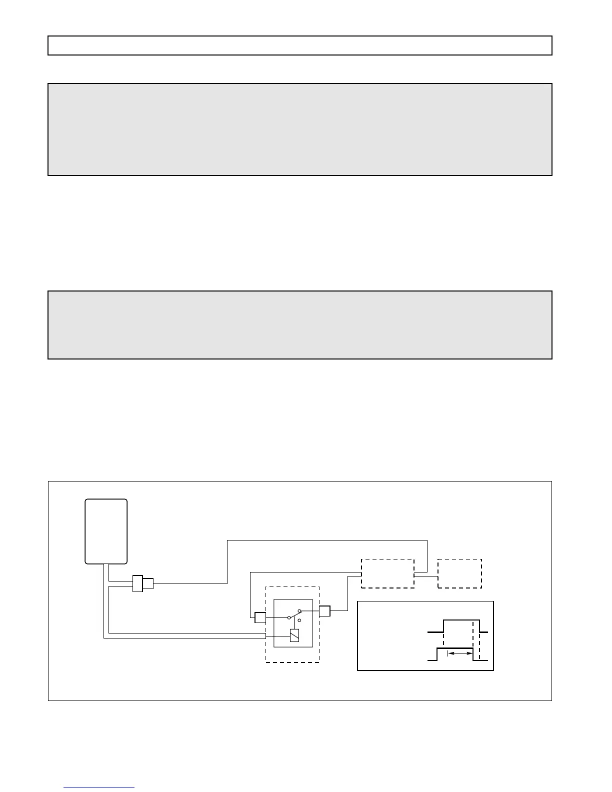
SHIFT IN PROCESS/SHIFT ENABLE
USES: Used to reduce engine power during a shift for high horsepower applications.
VARIABLES TO SPECIFY: None
VOCATIONS: Oil field pumping
OPERATING PROCEDURE
1. ECU sends signal (“Shift in Process”) to powertrain module that a shift is being requested.
2. Powertrain module reduces engine power and sends a signal to ECU (“Shift Enable”)
indicating that it is OK to shift.
3. ECU commands shift. When shift is completed, “Shift in Process” output turns off.
4. Powertrain module turns off the Shift Enable signal.
Figure P–20. Shift in Process/Shift Enable
WARNING!
If this function is enabled in the shift calibration, the function MUST be
integrated into the vehicle wiring. If the function is available in the shift
calibration but will not be used in the vehicle, it MUST be disabled in the
calibration.
E1
NC
COM
VIM
WIRE 117
SHIFT ENABLE
WIRE 125 SHIFT IN PROCESS
Relay shown de-energized
ENGINE
FUEL
CONTROL
POWERTRAIN
CONTROL
MODULE
NO
D1
OFF
ON
SHIFT
ENABLE
TYPICAL SHIFT
SHIFT IN
PROCESS
OFF
ON
V05025
NOTE: This function must NOT be used when the
transmission is used for vehicle propulsion.
SHIFT
16
ECU
VIW
CONNECTOR