WTEC II ELECTRONIC CONTROLS TROUBLESHOOTING MANUAL
P–32 Copyright © 1998 General Motors Corp.
APPENDIX P — INPUT/OUTPUT FUNCTIONS
WARNING!
These schematics show the intended use of the specified controls features which
have been validated in the configuration shown. Any miswiring or use of these
features which differs from that shown could result in damage to equipment or
property, personal injury, or loss of life. ALLISON TRANSMISSION IS NOT
LIABLE FOR THE CONSEQUENCES ASSOCIATED WITH MISWIRING
OR UNINTENDED USE OF THESE FEATURES.
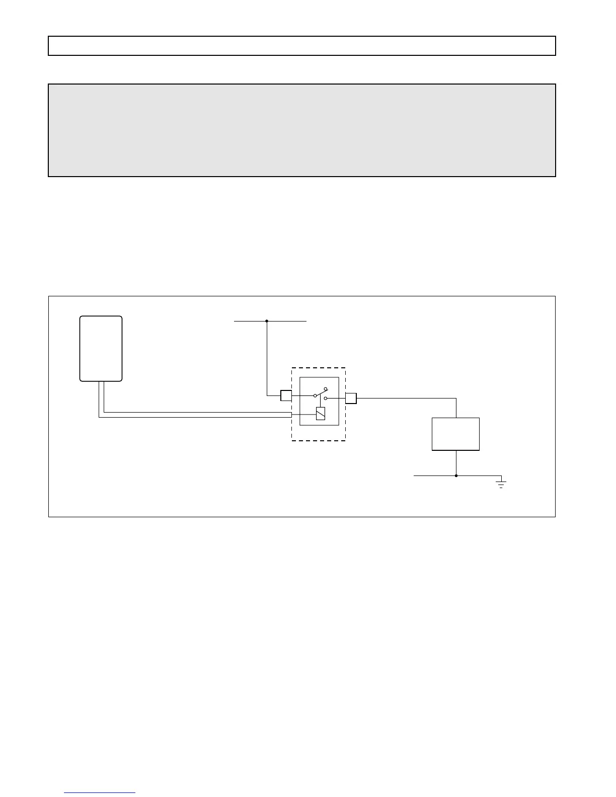
RANGE INDICATOR
USES: Used with auxiliary vehicle systems to permit operation only in specified transmission range(s).
VARIABLES TO SPECIFY: Range or ranges to be indicated
VOCATIONS: Various
Figure P–31. Range Indicator
A2
NC
COM
VIM
Relay shown de-energized
SWITCHED
POWER
WIRE 114 RANGE INDICATOR
NO
A3
V05035
AUXILIARY
VEHICLE
SYSTEM
Contacts close when transmission
is in specified range or ranges.
ECU