Copyright © 1998 General Motors Corp. 1–3
GENERAL DESCRIPTION
WTEC II ELECTRONIC CONTROLS TROUBLESHOOTING MANUAL
1–2. ELECTRONIC CONTROL UNIT (ECU)
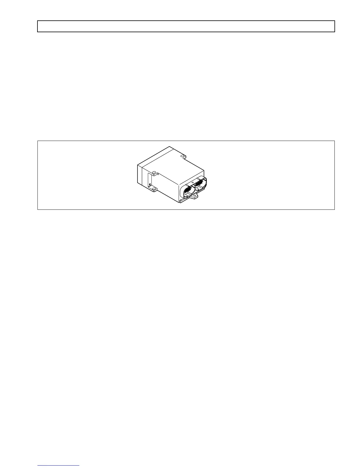
The ECU (Figure 1–4) contains the microcomputer which is the brain of the control system. The ECU receives and
processes information defining: shift selector position, throttle position, sump/retarder temperature, engine speed,
turbine speed, and transmission output speed. The ECU uses the information to control transmission solenoids and
valves, supply system status, and provide diagnostic information.
The ECU contains an Electronically Erasable Programmable Read Only Memory (EEPROM) which is
programmed with the shift calibration and other data for a specific transmission assembly, engine, and vehicle
vocation.
Figure 1–4. Electronic Control Unit (ECU)
1–3. SHIFT SELECTOR
Pushbutton and lever shift selectors are available for the WT Series. Either shift selector may be ordered attached to
(integral with), or remote from, the ECU. Both shift selectors are equipped with a digital display. However, the
strip pushbutton shift selector does not have a digital display.
On the shift selectors, between the range selected and the range monitored (attained) digits, is a
MODE ON
indicator position. During normal transmission operation
MODE ON
indicates that a secondary or special
operating condition has been selected by pressing the
MODE
button. In diagnostic display mode,
MODE ON
indicates the displayed diagnostic code is active. There is a
SERVICE
indicator icon under the
MODE ON
indicator. It is illuminated when codes 21 XX, 63 00, and 66 00 are active (for ECUs programmed after 9/26/94).
When a transmission fault occurs that causes the
DO NOT SHIFT
light to turn on, the shift selector sounds a tone
to indicate transmission shifting is restricted.
A. Pushbutton Shift Selector
(Figure 1–5)
The full-function pushbutton shift selector has six (6) buttons and a digital display. The six buttons
are:
R
(Reverse),
N
(Neutral),
D
(Drive),
⇑ (
Up
)
,
⇓ (
Down
)
, and
MODE
. Manual forward range
downshifts; upshifts are made by pressing the
⇑ (
Up
)
or
⇓ (
Down
)
arrow buttons after selecting
D
(Drive). The
N
(Neutral) button has a raised lip to aid in finding it by touch. The digital display
on the pushbutton selector indicates the range selected on the left side and the range monitored
(attained) on the right side. The
MODE
button is pressed to select a secondary or special operating
condition, such as ECONOMY shift schedule. The vehicle dimmer-control changes display
brightness. Diagnostic information is obtained by pressing the
⇑
(Up) and
⇓
(Down) arrow buttons
at the same time.
V00626.01
ECU