Copyright © 1998 General Motors Corp. D–17
WTEC II ELECTRONIC CONTROLS TROUBLESHOOTING MANUAL
APPENDIX D — WIRE/CONNECTOR CHART
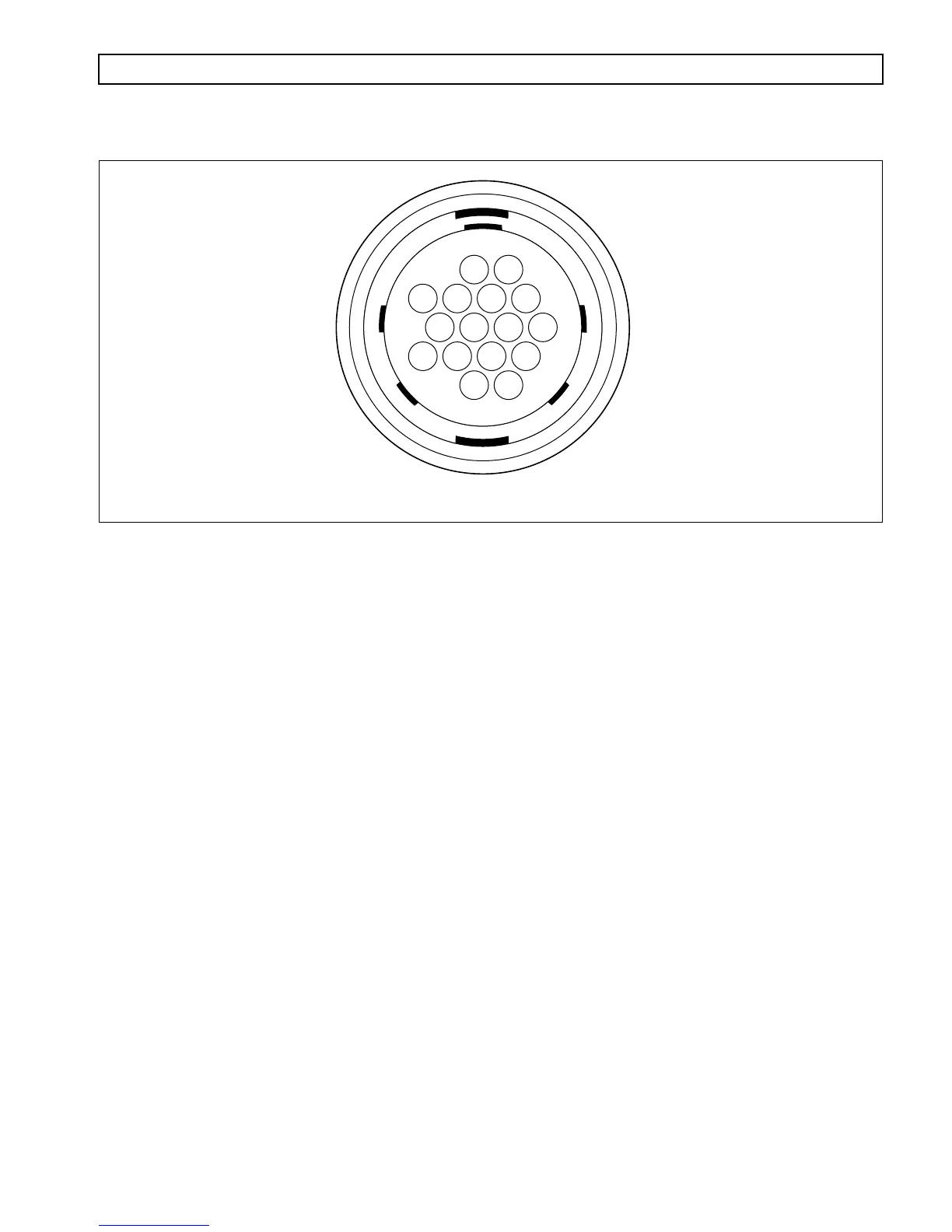
Figure D–13. VIW (Amp) Connector
VIW (AMP) CONNECTOR
Terminal No. Color Wire No. Description Termination Point(s)
1 Green 105 Spec Function Output 5 (–) ECU, A5
2 Blue 118 Spec Function Input 3 (+) ECU, A18
3 Yellow 119 Spec Function Input 4 (+) ECU, A19
4 Reserved
5 Orange 137 Spec Function Input 7 (–) ECU, B3
6 White 142B Serial Communication (+) ECU, B8; DDR, J
7 Blue 151B Serial Communication (–) ECU, B17; DDR, K
8 Yellow 153 Spec Function Input 2 (–) ECU, B19
9 Green 155 Spec Function Input 1 (–) ECU, B21
10 157 Reserved
11 158 Reserved
12 White 154 Spec Function Input ECU, B20
5 (–) ABS
13 Yellow 161B Signal Ground ECU, B27; Trans, F2
14 Blue 163 Spec Function Input 6 (–) ECU, B29
15 143A Reserved
16 Green 117 Spec Function Input 8 (–) ECU, A17
V00647.01
98710
4
LOOKING INTO END VIEW OF CONNECTOR ON EXTERNAL WIRING HARNESS
563
12
13 12 1114
16 15