WTEC II ELECTRONIC CONTROLS TROUBLESHOOTING MANUAL
E–52 Copyright © 1998 General Motors Corp.
APPENDIX E — CONNECTOR PART NUMBERS, TERMINAL PART
NUMBERS, TOOL PART NUMBERS, AND REPAIR INSTRUCTIONS
1–14. REPAIR OF A BROKEN WIRE WITH IN-LINE BUTT SPLICE
A. Connector Check Before Repair
NOTE: Before repairing or replacing wiring harness, sensor, solenoid, switch, or ECU as indicated for a
diagnosed problem, follow the procedure below:
1. Disconnect the connector or connectors associated with the problem and inspect for:
• Bent terminals
• Broken terminals
• Dirty terminals
• Pushed back terminals
• Missing terminals
• Condition of mating tabs
• Condition of mating terminals
Ensure that terminals are secure in the connector. Clean, straighten, or replace parts as required.
2. Reconnect all previous unmated connectors. Ensure connectors are fully inserted or twisted until
they lock in place. Connectors with locking tabs make an audible “click” when the lock is
engaged.
3. If trouble recurs after starting the vehicle, follow proper repair procedures for trouble code or
complaint.
4. If trouble does not recur, or if the correct repairs and/or replacements have been made, the problem
should be corrected.
B. Special Tools
• Heat Gun, J 25070 or equivalent
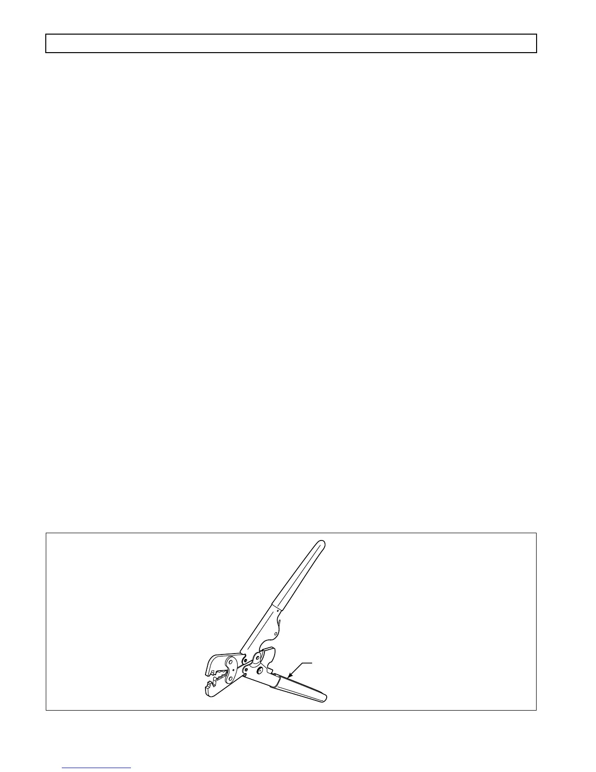
• Crimping Tool for Pre-insulated Crimp J 38125-8 (refer to Figure E–15)
NOTE: Use crimping anvils “F” and “G.”
• Wire Strippers, J 35615
• Splices P/N 23046604 14–16 AWG
• Splices P/N 23046605 18–22 AWG
\
Figure E–15. Crimper J 38125-8
F
G
J 38125-8
V01694