Copyright © 1998 General Motors Corp. F–1
WTEC II ELECTRONIC CONTROLS TROUBLESHOOTING MANUAL
APPENDIX F — THROTTLE POSITION SENSOR ADJUSTMENT
A. Description of Operation
(Figure F–1)
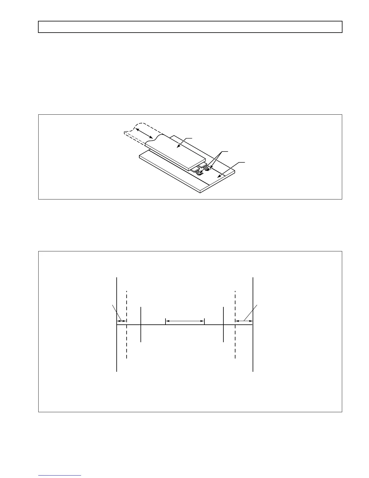
1. To properly communicate throttle position to the Electronic Control Unit (ECU), the throttle
position sensor must convert its mechanical movement to an electrical form the ECU can
understand. To accomplish this, contacts move across a resistive strip inside the sensor which
translates position into voltage.
Figure F–1. Throttle Position to Voltage Conversion
2. Each position gives a different voltage. The ECU then converts the voltage to counts. Each count
corresponds to approximately .179 mm (.007 inch) of throttle sensor movement. Figure F–2
diagrams the counts and throttle movement relationship.
Figure F–2. Throttle Position Determination Diagram
V00656.01
THROTTLE POSITION LINKAGE
RESISTIVE STRIP
CONTACTS
0 COUNT
14 COUNTS
50 COUNTS
CLOSED
THROTTLE
WIDE OPEN
THROTTLE
233 COUNTS
255 COUNTS
200 COUNTS
APPROX.
19 mm (0.75 in.) STROKE
FULLY
EXTENDED
ERROR
ZONE
ERROR
ZONE
FULLY
RETRACTED
(AT REST)
Total Stroke
CT–WOT
15.2 mm–22.9 mm
(0.63 in.–0.9 in.)
85–130 Counts
Adjust so total stroke is within
50–200 count band
0 mm
2.5 mm
(0.1 in.)
40.6 mm
(1.6 in.)
45.7 mm
(1.8 in.)
V00429.04