WTEC II ELECTRONIC CONTROLS TROUBLESHOOTING MANUAL
D–12 Copyright © 1998 General Motors Corp.
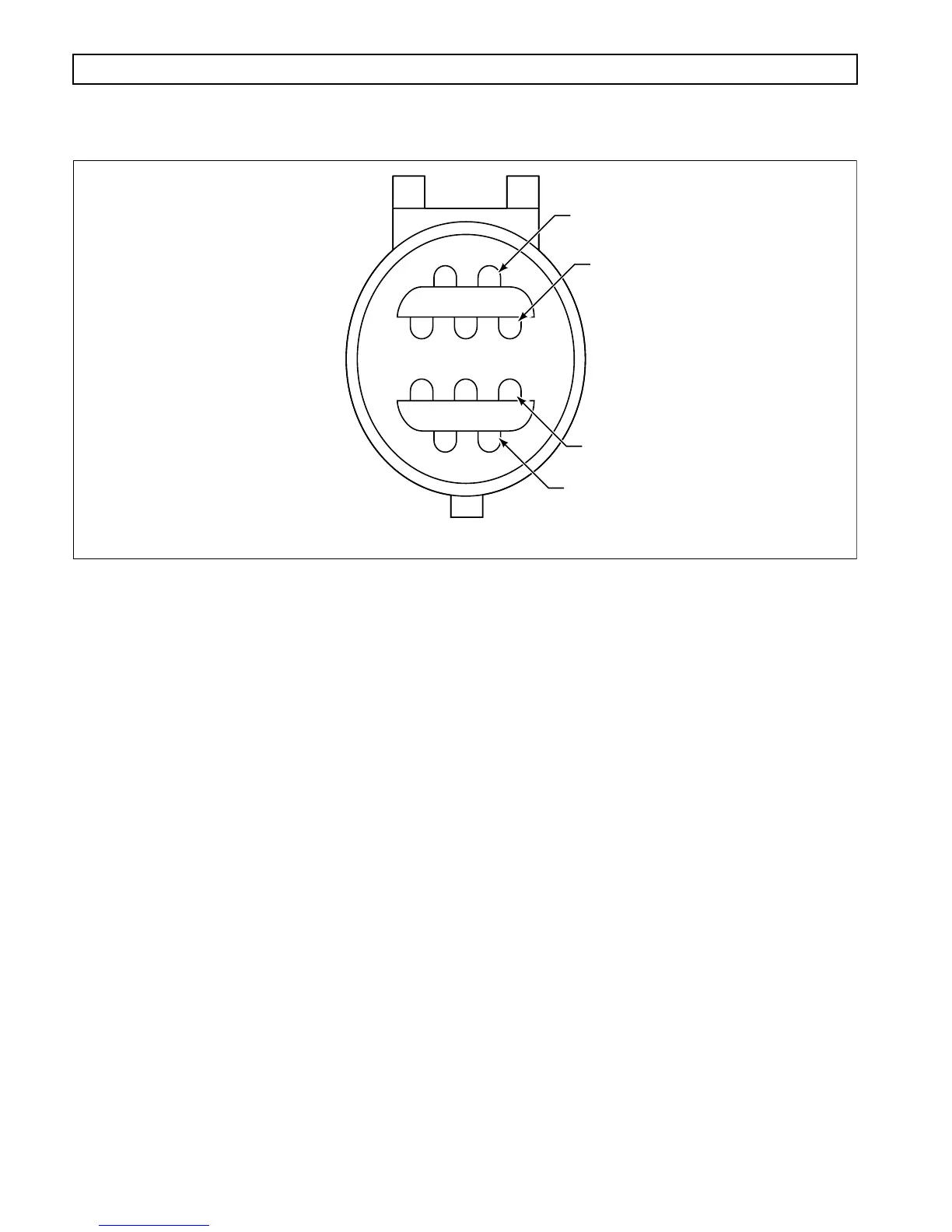
APPENDIX D — WIRE/CONNECTOR CHART
Figure D–8. RSI Connector
REMOTE SERIAL INTERFACE CONNECTOR
Terminal No. Color Wire No. Description Termination Point(s)
1 Red 136 Battery (+) ECU, B2; VIM Conn, E1
2 Orange Jumper RSI Conn, 3 (Clip Jumper Wire
When Remote Selector
is Primary)
3 Orange Jumper RSI Conn, 2
4 Yellow 168 Remote Serial ECU, B34
Interface (+)
5 Violet 160 Remote Serial ECU, B26
Interface (–)
6 Yellow 108 Remote Power Wakeup ECU, A8
7 Black 143 Battery (–) ECU, B9; VIM Conn, A1;
Battery (–)
8 Reserved
9 Reserved
10 Reserved
V00642.02
1
3
9
6