WTEC II ELECTRONIC CONTROLS TROUBLESHOOTING MANUAL
D–32 Copyright © 1998 General Motors Corp.
APPENDIX D — WIRE/CONNECTOR CHART
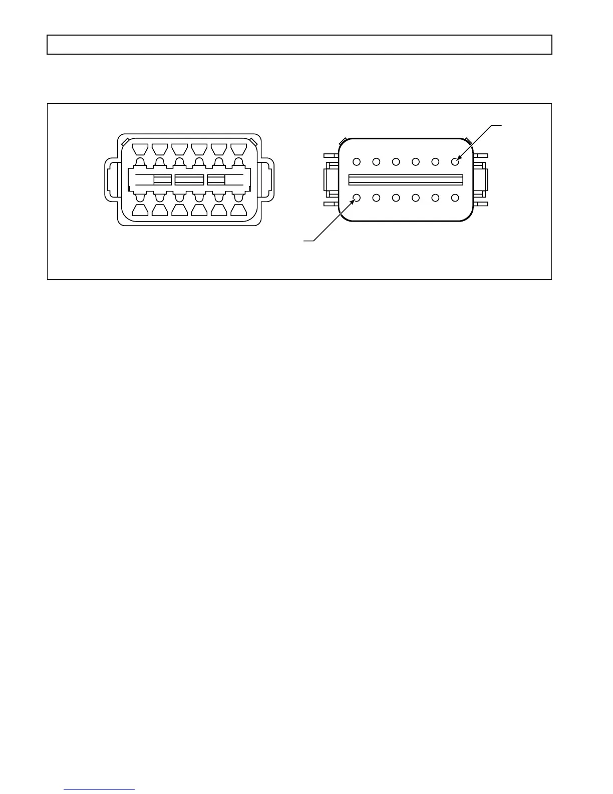
Figure D–25. Navistar Deutsch DT Series VIW Connector
VIW A (GRAY)
Current Configuration Former Configuration
Terminal No. Color Wire No. Description Wire No. Description Termination Point(s)
1 Yellow 161C Signal Ground 161B Same as Current Splice to 161A
2 Blue 163 SFI6 163 Same as Current ECU, B29
3 Yellow 325CM SFO4Com 320 Same as Current VIM B, E1
4 Green 325NC SFO4NC 321 Same as Current VIM B, D1
5 Yellow 119 SFI4 153 SFI2 ECU, A19
6 Yellow 332CM SFO2Com 315 SFO1Com VIM B, E2
7 Green 332NC SFO2NC 316 SFO1NC VIM B, D2
8 Blue 332NO SFO2NO 317 SFO1NO VIM B, E3
9 Green 105 SFO5 105 Same as Current ECU, A5
10 Blue 151B SCI – 151B Same as Current Splice to 151A
11 White 142B SCI + 142B Same as Current Splice to 142A
12 Orange 137 SF17 117 SFI8 ECU, B3
VIW B (BLACK)
Current Configuration Former Configuration
Terminal No. Color Wire No. Description Wire No. Description Termination Point(s)
1 Orange 346 Ignition Signal 303 Same as Current VIM B, C1
2 White 358 Dimmer 324 Same as Current VIM B, J3
3 White 142A SCI + 142A Same as Current ECU, B8
4 Blue 151A SCI – 151A Same as Current ECU, B17
5 White 315 DNS 319 Same as Current VIM B, K3
6 Black 143B Battery Ground 143B Same as Current Splice to 143A
1
7
V01680
(continued on the next page)