Copyright © 1998 General Motors Corp. P–21
WTEC II ELECTRONIC CONTROLS TROUBLESHOOTING MANUAL
APPENDIX P — INPUT/OUTPUT FUNCTIONS
WARNING!
These schematics show the intended use of the specified controls features which
have been validated in the configuration shown. Any miswiring or use of these
features which differs from that shown could result in damage to equipment or
property, personal injury, or loss of life. ALLISON TRANSMISSION IS NOT
LIABLE FOR THE CONSEQUENCES ASSOCIATED WITH MISWIRING
OR UNINTENDED USE OF THESE FEATURES.
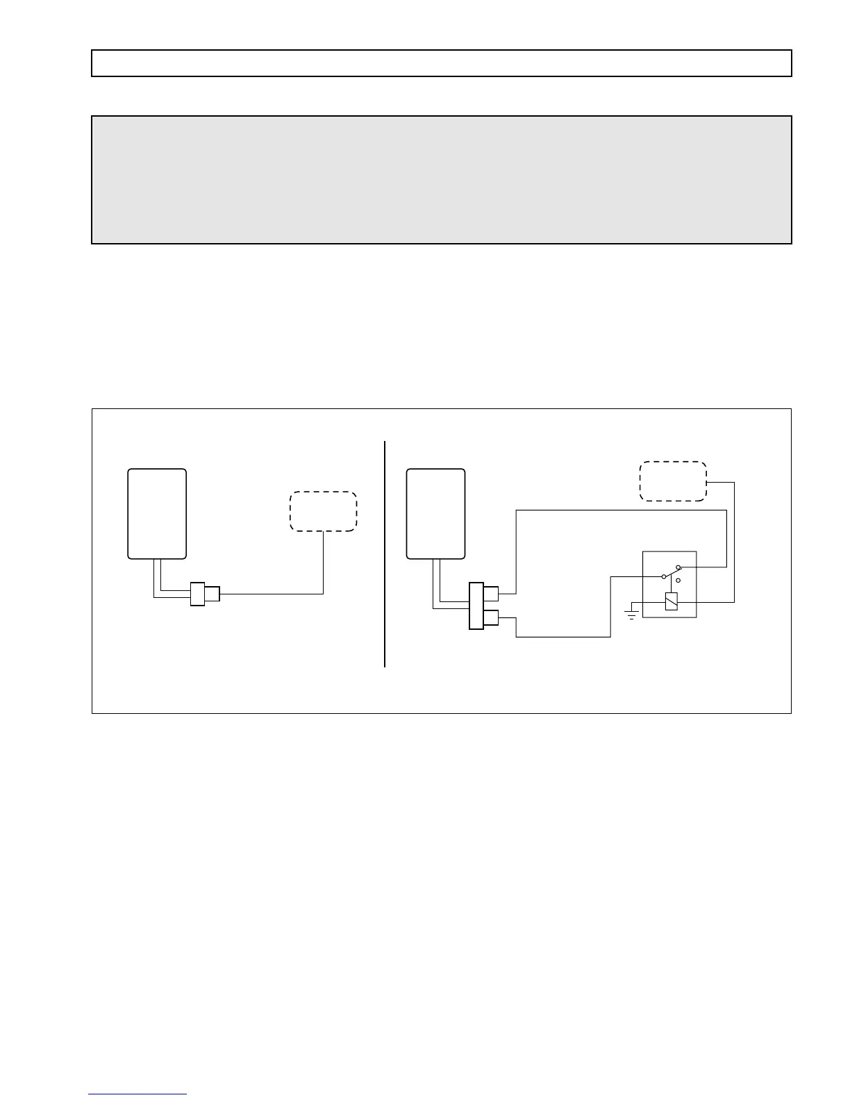
ANTI-LOCK BRAKE RESPONSE
USES: Signals the ECU when ABS function is active, so that lockup clutch and retarder will be disabled.
VARIABLES TO SPECIFY: None
VOCATIONS: Various
Figure P–21. Anti-Lock Brake Response
NOTE: This signal must stay constantly low during the duration of the ABS-active period. When ABS switches
off, the transmission lockup clutch is re-applied, and retarder or engine-brake operation is resumed.
CUSTOMER-
FURNISHED
RELAY
ABS
CONTROLS
V05026
WIRE 161B
SIGNAL GROUND
WIRE 154 (–)
ABS INPUT
WIRE 154 (–)
ABS INPUT
13
12
ECU
VIW
CONNECTOR
NC
COM
Relay shown
de-energized
NO
ABS
CONTROLS
12
ECU
This configuration is to be used if
ABS output is a negative (–) signal.
This optional configuration is to be used if
ABS output is a positive (+) signal.