WTEC II ELECTRONIC CONTROLS TROUBLESHOOTING MANUAL
G–2 Copyright © 1998 General Motors Corp.
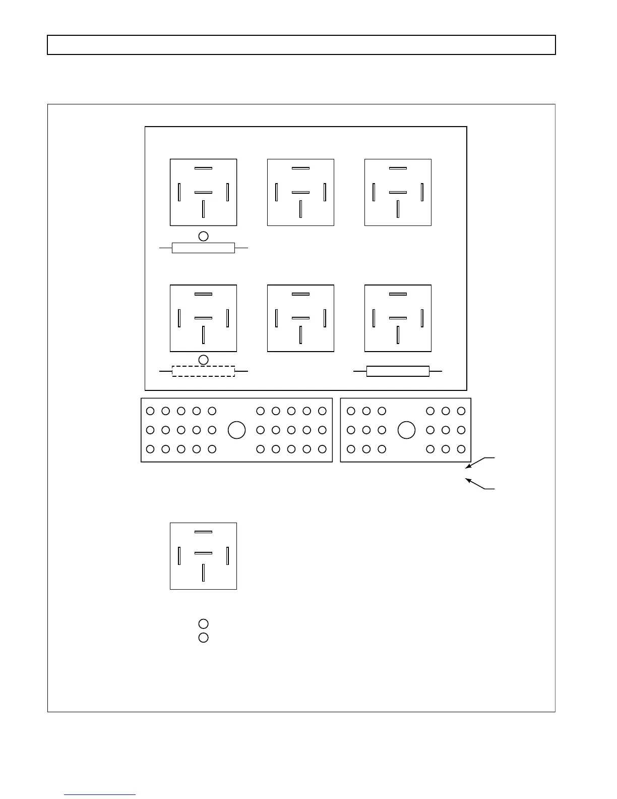
APPENDIX G — MISCELLANEOUS ITEMS
Figure G–2. VIM Components Location and Pin-Out Diagram
A3/30
B2/30
A2/30
S3/18 C1/30
S1/18
S1/18
S1/18
S1/18
D1/30
E1/30
C1/30 N2/18
F3/30
C2/30
F2/30
P2/18 K1 & 2/30
A1/30
B1/30
S2/18 C1/30
C1/30
IGNITION FUSE
S1/18
E3/30
D2/30
E2/30
1
2
3
ABCDE
30-WAY CONNECTOR
(PIN ID/30)
PIN NUMBERING ON
BOTTOM OF RELAY
Ignition fuse position in early VIM
18-WAY CONNECTOR
(PIN ID/18)
See page D-24 for
wire/terminal usage.
See page D-25 for
wire/terminal usage.
FGHJK LMN PRS
ABC DEF
3
2
1
M1/18 C1/30
(-)
(K4)
WIRE 114/SFO 1
87
87A
30
86
85
(K1)
WIRE 113/REVERSE WARNING
(K2)
WIRE 132/SFO 2
(K3)
WIRE 123/NEUTRAL START
(K5)
WIRE 125/SFO 4
(K6)
WIRE 112/SFO 3
(+)
L1 & 2/18
F1/30
G1/30
P1/18
K1 & 2/30
S1/18C1/30
IGNITION FUSE
R1 & 2/18J1 & 2/30
MAIN FUSE
V01814.01
2
1
1
Ignition fuse must be in place and not open for there to be
continuity between pins C1/30 and R1/18
2
TERMINAL
BOARD
IDENTIFICATION
HARNESS
CONNECTOR
IDENTIFICATION