WTEC II ELECTRONIC CONTROLS TROUBLESHOOTING MANUAL
D–20 Copyright © 1998 General Motors Corp.
APPENDIX D — WIRE/CONNECTOR CHART
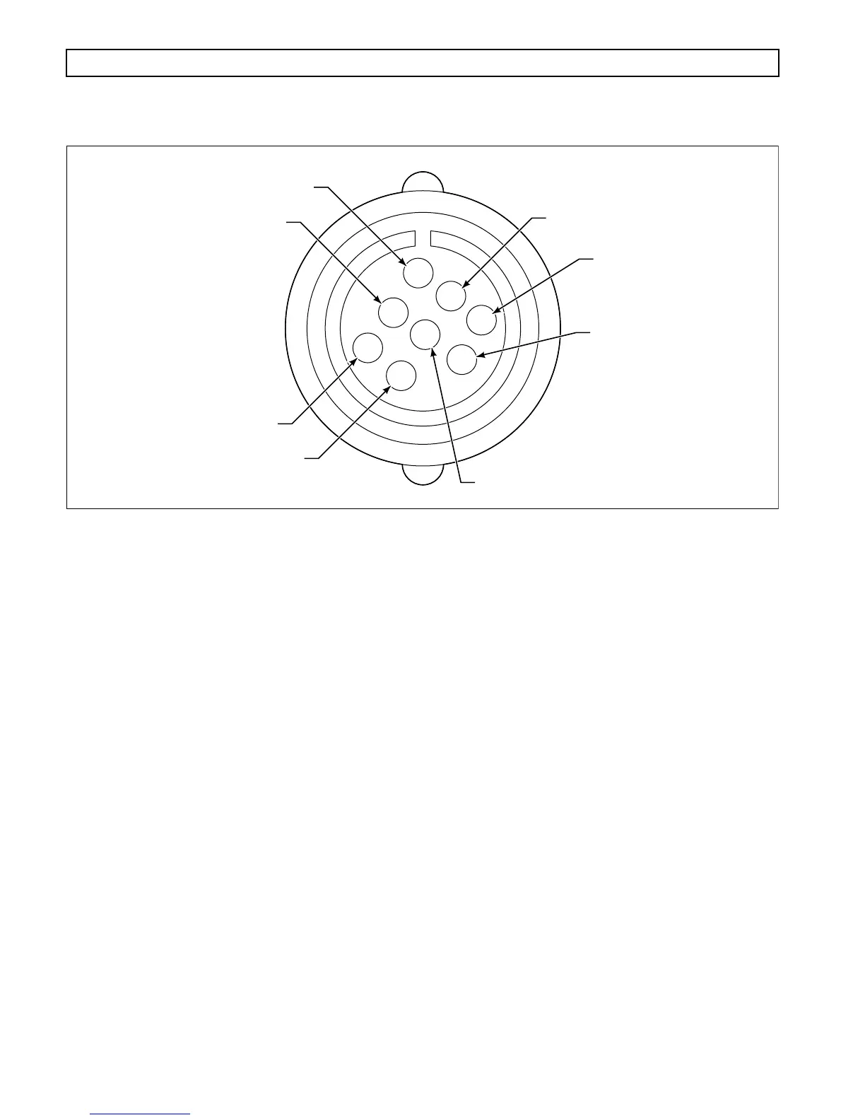
Figure D–16. Retarder Connector (MD/B 300/B 400)
RETARDER CONNECTOR — MD/B 300/B 400
Terminal No. Color Wire No. Description Termination Point(s)
A Yellow 134 K (Rtdr Enable) Solenoid Hi ECU, A34
B Blue 109 K (Rtdr Enable) Solenoid Lo ECU, A9
C Yellow 139 Output Speed Sensor Hi ECU, B5
D Green 148 Output Speed Sensor Lo ECU, B14
E Orange 138 Retarder Temperature ECU, B4
F Green 135C Analog Ground ECU, B1; Trans Conn,
Term G2; TPS A
V00646
B
D
C
H
A
G
F
E