6–70 Copyright © 1998 General Motors Corp.
WTEC II ELECTRONIC CONTROLS TROUBLESHOOTING MANUAL
PROBING THE CONNECTOR
When testing the control system from the feedthrough connector with the internal harness connected, contact with
the following pairs of terminals will result in resistance measurements of two solenoids through a shared ground.
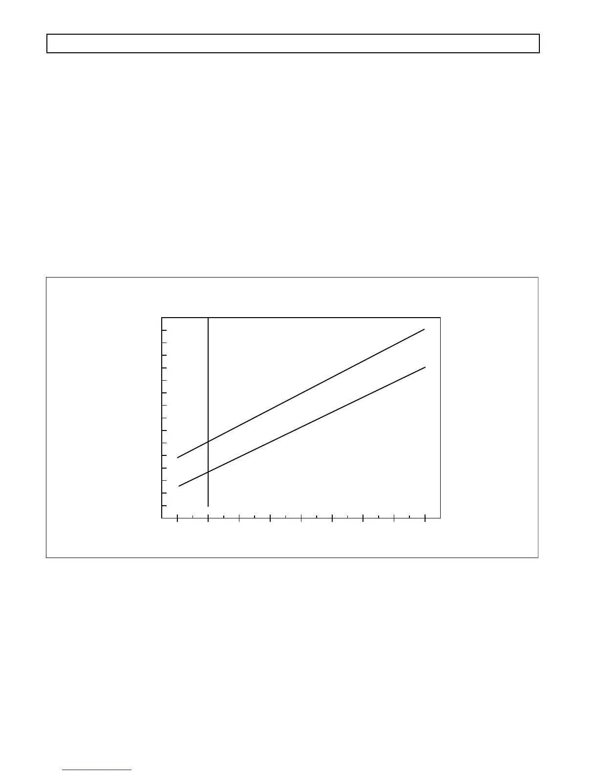
The resistance should be twice that of a single solenoid. Refer to Figure 6–26 for solenoid resistance versus
temperature.
Figure 6–26. Solenoid Resistance vs. Temperature
Troubleshooting:
1. Make sure the transmission connector is tightly connected. If the connector is properly connected,
disconnect the wiring harness at the transmission. Check the connector for water contamination
and for corroded or damaged terminals. Clean or replace as necessary.
2. Test solenoid circuit at the transmission connector for shorts between the solenoid circuit being
diagnosed and all other terminals in the connector. This test may be simplified by using the
J 38850 test tool. Refer to the system schematic and/or chart to identify wires in the internal
harness which are connected. If a short is found, isolate and repair the short. The short will
probably be in the internal wiring harness.
Terminals
Solenoids Which
Share Ground
A1, D1 A, D
B1, E1 B, E
C1, F1 C, G
V00719.01
MAXIMUM OHMS
WT SOLENOID RESISTANCE
SPEC VALUE=3.26±.2 OHMS AT 20°C
MINIMUM OHMS
SOLENOID RESISTANCE IN OHMS
4.8
5.2
4.6
5
4.4
4.2
4
3.8
3.6
3.4
3.2
3
2.8
2.6
2.4
2.2
2
-20 0 20 40 60 80 100 120 140
4 32 68 104 140 176 212 248 284
SUMP TEMPERATURE IN °F
SUMP TEMPERATURE IN °C
CODE 42 XX — SHORT-TO-BATTERY IN SOLENOID CIRCUIT
(Figures 6–24, 6–25)