WTEC II ELECTRONIC CONTROLS TROUBLESHOOTING MANUAL
D–28 Copyright © 1998 General Motors Corp.
APPENDIX D — WIRE/CONNECTOR CHART
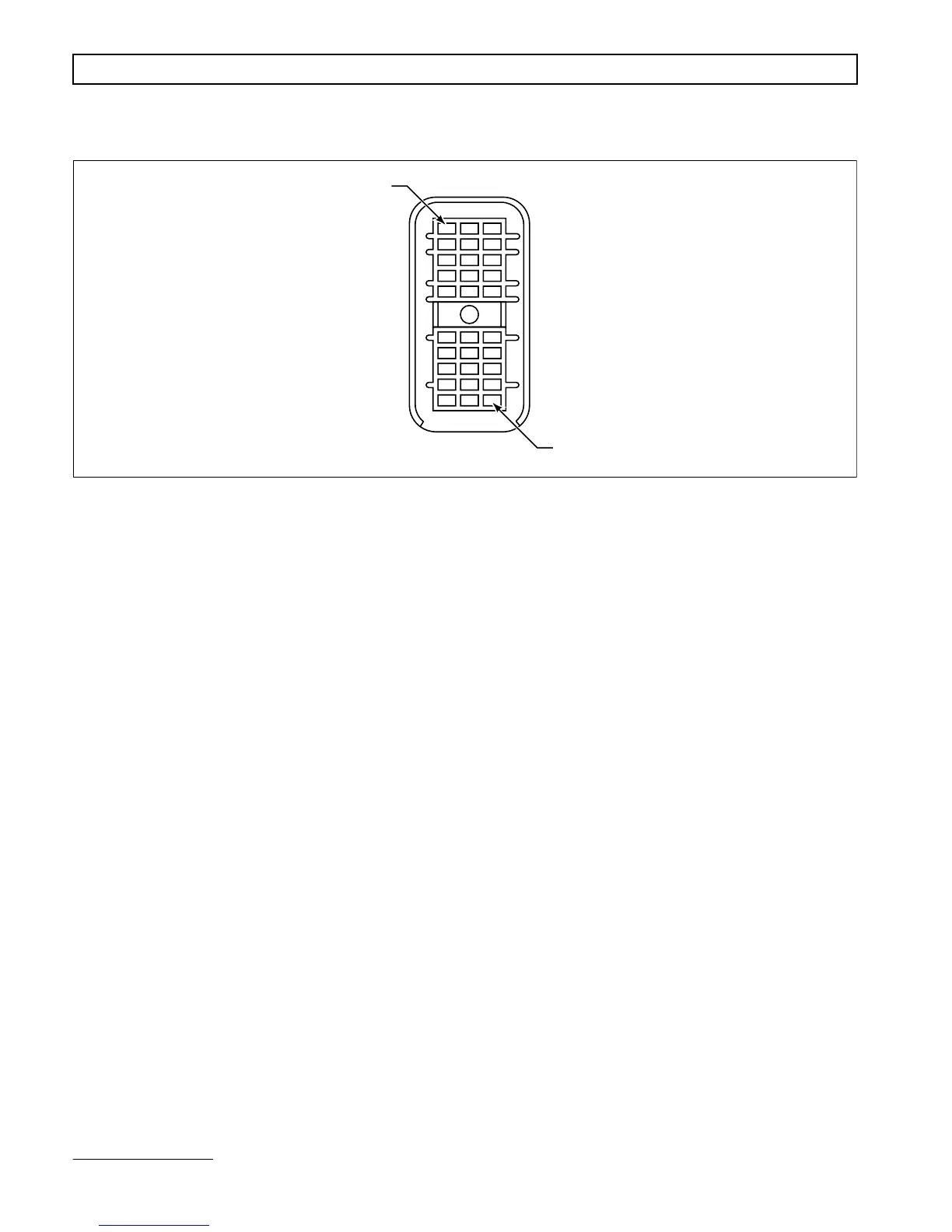
Figure D–21. VIM Connector (Harness)
* Termination Points are determined by OEM electrical system design.
VIM CONNECTOR (HARNESS 30-WAY)
Terminal No. Color Wire No. Description Termination Point(s)*
A1 Blue 313NO Reverse Warning Relay — Normally Open
A2 Yellow 314CM Output Wire 114 Relay — Common
A3 Blue 314NO Output Wire 114 Relay — Normally Open
B1 Yellow 313CM Reverse Warning Relay — Common
B2 Green 314NC Output Wire 114 Relay — Normally Closed
B3 Reserved
C1 Orange 346 Ignition Power
C2 Green 312NC Output Wire 112 Relay — Normally Closed
C3 Reserved
D1 Green 325NC Output Wire 125 Relay — Normally Closed
D2 Green 332NC Output Wire 132 Relay — Normally Closed
D3 Reserved
E1 Yellow 325CM Output Wire 125 Relay — Common
E2 Yellow 332CM Output Wire 132 Relay — Common
E3 Blue 332NO Output Wire 132 Relay — Normally Open
F1 Blue 323NO Neutral Start Relay — Normally Open
F2 Yellow 312CM Output Wire 112 Relay — Common
F3 Blue 312NO Output Wire 112 Relay — Normally Open
G1 Yellow 323CM Neutral Start Relay — Common
G2 Reserved
G3 Reserved
H1 Reserved
H2 White 357UF Speedometer — Unfiltered
H3 Reserved
J1 Red 336A Battery Power
J2 Red 336C Battery Power
J3 White 358 Dimmer
K1 Black 343A Battery Ground
K2 Black 343C Battery Ground
K3 White 315 “DO NOT SHIFT” Light
A1
K3
V01240