WTEC II ELECTRONIC CONTROLS TROUBLESHOOTING MANUAL
P–34 Copyright © 1998 General Motors Corp.
APPENDIX P — INPUT/OUTPUT FUNCTIONS
WARNING!
These schematics show the intended use of the specified controls features which
have been validated in the configuration shown. Any miswiring or use of these
features which differs from that shown could result in damage to equipment or
property, personal injury, or loss of life. ALLISON TRANSMISSION IS NOT
LIABLE FOR THE CONSEQUENCES ASSOCIATED WITH MISWIRING
OR UNINTENDED USE OF THESE FEATURES.
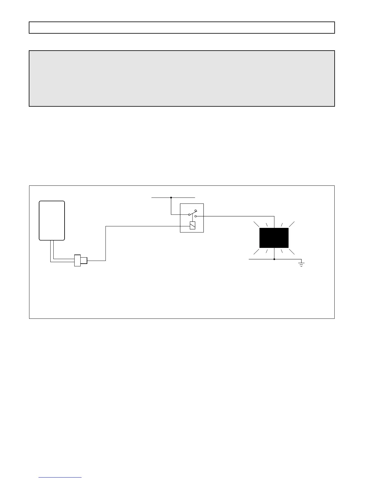
OUTPUT SPEED INDICATOR — B
USES: To signal that the transmission output shaft has exceeded a specified value.
VARIABLES TO SPECIFY: Rpm to turn output ON and to turn output OFF. The ON value must be higher than
the OFF value.
VOCATIONS: Various
Figure P–33. Output Speed Indicator — B
CUSTOMER-
FURNISHED
RELAY
NC
COM
Relay shown
de-energized
SWITCHED
POWER
NO
V05037
TRANSMISSION
OR VEHICLE
OVERSPEED
INDICATOR
WIRE 105
OUTPUT SPEED INDICATOR
NOTE: The ON and OFF control values for this function may
be specified within the same range of values which are
permitted for “Output Speed Indicator – A”. However, the
control values for this function may not be adjusted using the
Pro-Link
®
Diagnostic Tool. Therefore, if adjustment of these
values is a desirable feature, the “Output Speed Indicator – A”
function must be used.
1
ECU
VIW
CONNECTOR