Copyright © 1998 General Motors Corp. 6–47
DIAGNOSTIC CODES
WTEC II ELECTRONIC CONTROLS TROUBLESHOOTING MANUAL
Main code 25 occurs if the output speed sensor reports a zero speed reading while both engine and turbine speeds
are approximately equal, turbine speed is above a calibration value, and neutral is not selected or commanded.
Main code 25 indicates either the output speed sensor has failed or the required oncoming clutch or clutches did not
come on. Code 25 11 can be generated by a false turbine speed reading. This may be due to crosstalk between
solenoid and turbine speed sensor circuits caused by direct wire-to-wire short or by water in the electrical
connectors. See Section 4 for corrective action.
NOTE: If Code 25 XX is in memory at ECU initialization (ignition on) all display segments are illuminated.
Active Indicator Clearing Procedure:
•
Power down
•
Manual
•
Self-clearing
NOTE: Before troubleshooting, read Pages 6–17 and 6–18 of Section 6–5. Also, check battery and ECU input
voltages.
NOTE: Intermittent connections or lack of battery-direct power and ground connections can cause this and
other codes.
1. Check the transmission fluid level and ensure correct fluid level.
2. Check for the presence of Code 22 16. If Code 22 16 is in the code list, go to Code 22 XX section
and follow troubleshooting steps for Code 22 16.
3. Connect the Pro-Link
®
9000 with ignition on, engine off; check for indication of turbine speed. If
turbine speed is indicated, refer to Section 4–2 for corrective action.
4. If the output speed sensor and wiring are satisfactory, install pressure gauges into the appropriate
clutch pressure taps (see appropriate transmission Service Manual or Appendix B in this manual)
and make the shift again. See if either of the clutches has low or no pressure. Lack of pressure in
first range may be due to a G solenoid stuck closed.
5. If a clutch is leaking pressure, drain the fluid, remove the control module and check for damaged
valve body gaskets and stuck or sticky valves. If no problems are found, replace the solenoids for
the clutches used in the range indicated by the code (refer to Figure 6–1). Refer to the appropriate
transmission Service Manual for replacement procedure.
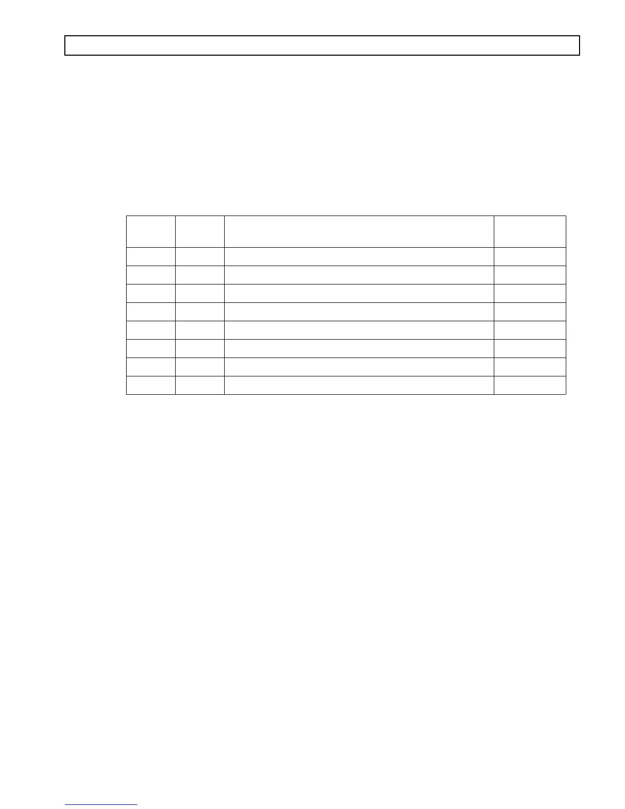
Main
Code
Subcode Meaning
Applied
Clutches
25 00 Output speed sensor, detected at zero speed, low range C3, C6
25 11 Output speed sensor, detected at zero speed, 1st range C1, C5
25 22 Output speed sensor, detected at zero speed, 2nd range C1, C4
25 33 Output speed sensor, detected at zero speed, 3rd range C1, C3
25 44 Output speed sensor, detected at zero speed, 4th range C1, C2
25 55 Output speed sensor, detected at zero speed, 5th range C2, C3
25 66 Output speed sensor, detected at zero speed, 6th range C2, C4
25 77 Output speed sensor, detected at zero speed, reverse C3, C5
CODE 25 XX — OUTPUT SPEED SENSOR, DETECTED AT ZERO SPEED,
X RANGE
(Figures 6–13, 6–14)