APPENDIX B: ELECTRICAL AND DATA CONNECTIONS
HF-2500A HIGH FREQUENCY WELD CONTROL
B-6 990-371
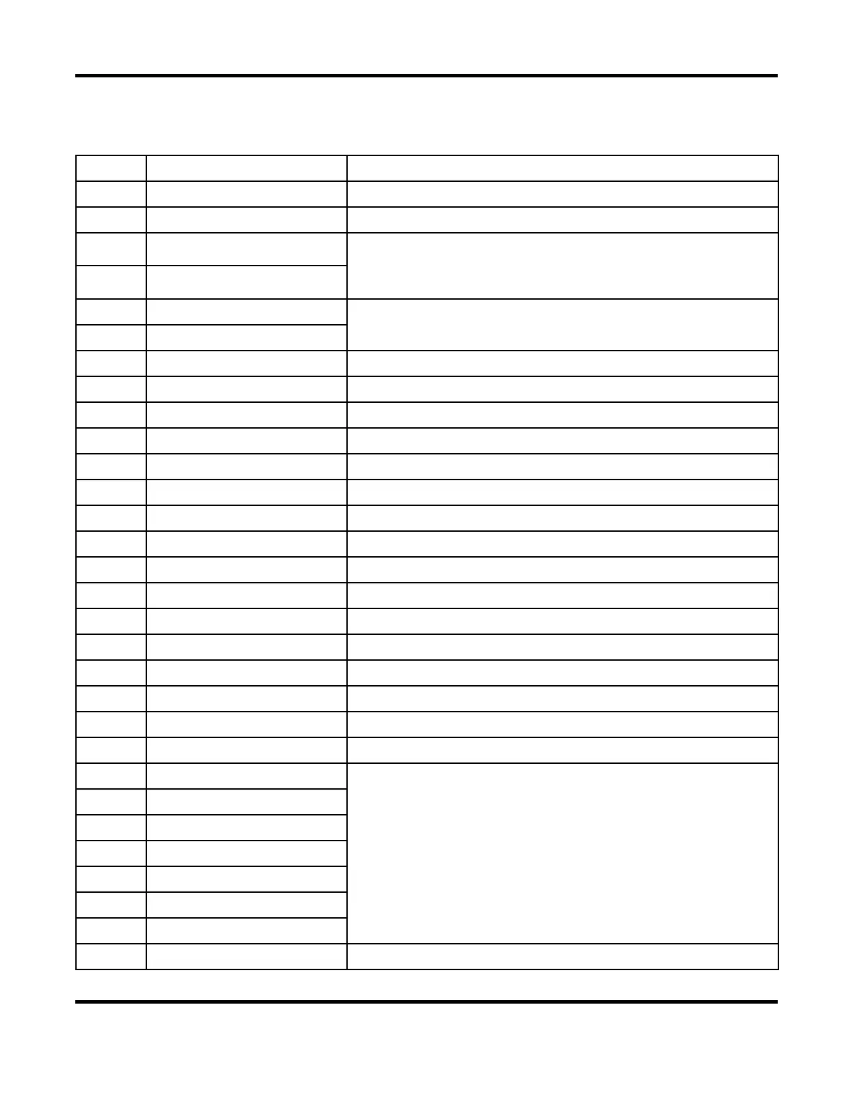
Input / Output Signals
Pin Signal Name Description
1
CHASSIS GROUND Chassis Ground
2
24COM NEGATIVE of internal 24 VDC power supply
3
HEAD_1
COMMON for air valve solenoid, switched
For 24 VDC operation: Connect other end of solenoid to +24V_OUT
For 24 VAC operation: Connect other end of solenoid to 24 VAC
4
HEAD_2
5
RELAY_5
Relay 5 output, dry contact, programmable
Contact rating: 24 VDC/AC, 1 amp
6
RELAY_5R
7
24COM NEGATIVE of internal 24 VDC power supply
8
24VAC 24 VAC power supply
9
Not active Not active
10
WELD_ABORT Weld Abort Input
11
FIRE 1 Fires unit
12
24COM NEGATIVE of internal 24 VDC power supply
13
WELD / NO_WELD Weld / No Weld Input. Functions as a weld enable.
14
Not active Not active
15
I/O COMMON COMMON terminal for pins 10, 13, 24 - 31
16
FOOT 1 Activates foot level stage 1
17
FOOT 2 Activates foot level stage 2
18
24COM NEGATIVE of internal 24 VDC power supply
19
FS1/FS2/FIRE_COM COMMON terminal for pins 11, 16, 17
20-21
+24V_OUT +24 VDC output of internal power supply, polyfused at 1 amp
22
I/O COMMON COMMON terminal for pins 10, 13, 24 - 31
23
24COM NEGATIVE of internal 24 VDC power supply
24
SCHEDULE 0
Binary Schedule input terminals, used for schedule selection
25
SCHEDULE 1
26
SCHEDULE 2
27
SCHEDULE 4
28
SCHEDULE 8
29
SCHEDULE 16
30
SCHEDULE 32
31
WELD_INHIBIT Inhibits weld