CHAPTER 5. OPERATING INSTRUCTIONS
HF-2500A HIGH FREQUENCY WELD CONTROL
990-371 5-11
PART CONDITIONER (Stop PULSE1)
stops Pulse 1 immediately after upper or lower
energy limits are exceeded, but allows Pulse 2 to fire. This function will not operate
if both pulses are joined without a cool time.
NOTE: See Section IV, Programming For Active Part Conditioning.
r making your selection the display will automatically return to the monitor screen.
Program the upper and lower limits for Pulse 2 by repeating Steps 4 through 6 above using the
keys for Pulse 2, entering appropriate values for Pulse 2.
• The monitor limit mode (current, voltage, power or resistance
different than the monitor limit mode for Pulse 1.
• To “fine tune” the monitor limits to very precise values, see Chapter 4,
Feedback Modes and Monitoring.
HOLD
will bring up the PULSE 2 OUT
OF LIMITS ACTION
screen. This
screen allows you to select the
action that the Power Supply will
take if the Pulse 2 upper or lower
PULSE 2 OUT OF LIMITS ACTION
1. none
2. STOP WELD
NUMBER Select, Page, RUN or MENU
NONE takes no action if upper or lower energy limits are exceeded.
STOP WELD stops PULSE 2 immediately after upper or lower energy limits are
exceeded.
After you have made your selection the
display will automatically return to the
MONITOR
screen.
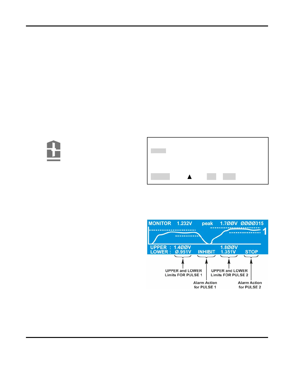
: The Power Supply adds dotted
lines to the appropriate graph to show the
programmed limits
.
The screen on the right shows how the
Limits
and Alarm actions appear when
an actual weld trace is displayed on the
LCD.
After entering or changing monitor limits, you must press either the appropriate
MONITOR
buttons to save the changes. If this is not done, the last input field will remain highlighted,
and the changes will not be saved to memory.
Any welds done in this condition will use the
older, unedited values still stored in the memory.