CHAPTER 5. OPERATING INSTRUCTIONS
HF-2500A HIGH FREQUENCY WELD CONTROL
5-12 990-371
NOTE: All lower limits apply only to the Pulse 1 and Pulse 2
WELD
periods. Lower limits do
not
cover any upslope or downslope periods. All upper limits apply to the entire Pulse 1 and
Pulse 2 periods, including their upslope and downslope periods.
12. Set an UPPER LIMIT and LOWER LIMIT using the procedures in Chapter 4, Using Feedback Modes
and Weld Monitoring. Perform a weld to see how the limits (dotted lines) appear compared to
the weld graph.
13. Raise or lower the UPPER LIMIT and LOWER LIMIT as necessary using the procedures in Chapter
4, Using Feedback Modes and Weld Monitoring.
14. To lengthen or shorten the time periods, go to the MONITOR screen.
15. Press the UPSLOPE key for PULSE 1 or PULSE 2 to get the MONITOR LIMITS screen.
INGNORE 1st
the beginning of the limit, IGNORE LAST
deletes time from the end of the limit.
This will not only shorten the limit time,
but depending on the amount of time
deleted on each end of the limit, the limit
will appear to move horizontally across
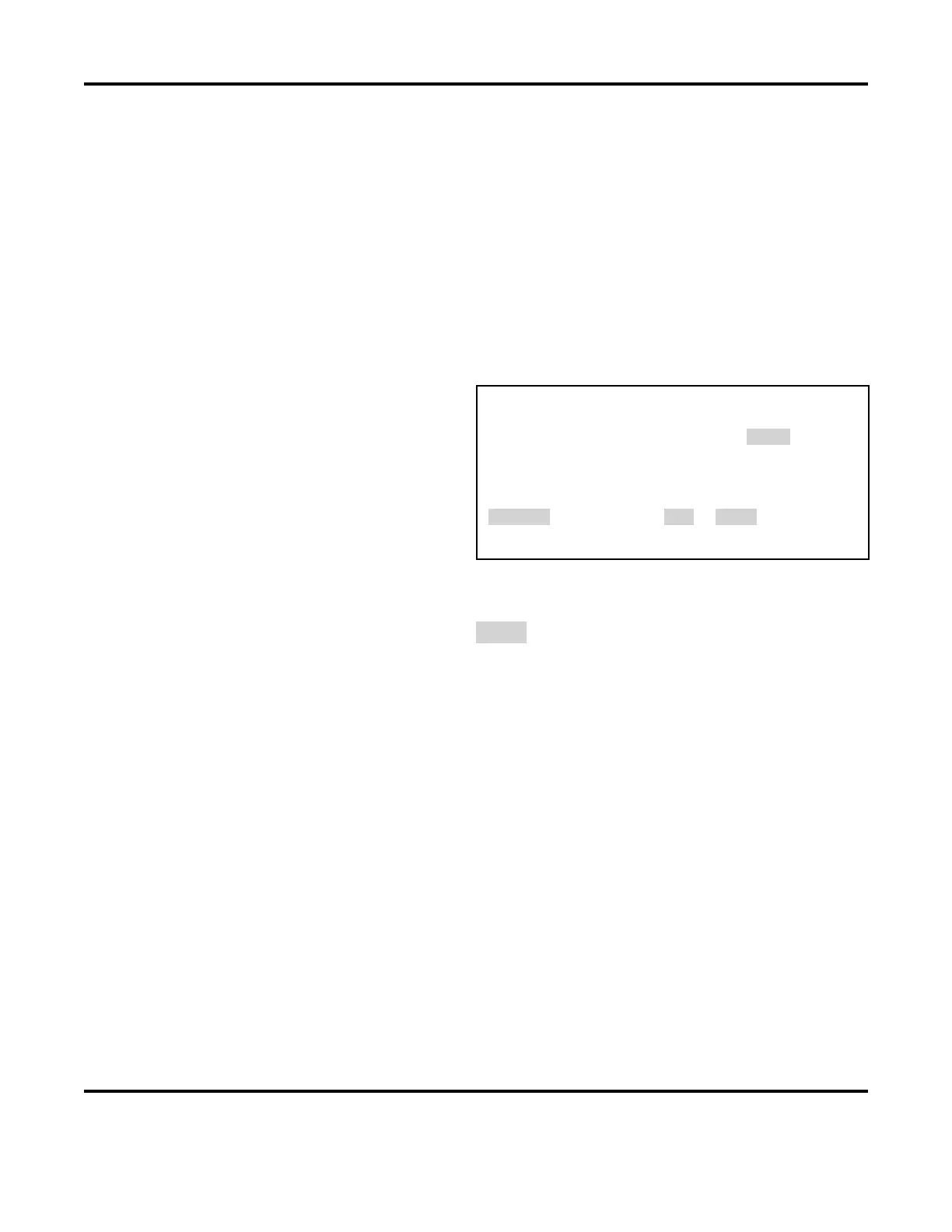
< PULSE 1 MONITOR LIMITS >
1. LOWER LIMIT IGNORE 1ST : 0.0 ms
2. LOWER LIMIT IGNORE LAST : 2.5 ms
3. UPPER LIMIT IGNORE 1ST : 0.0 ms
4. UPPER LIMIT IGNORE LAST : 0.0 ms
NUMBER Select an item, RUN or MENU
you to fit the LOWER LIMIT precisely into the waveform graph.
16. Use the numerical keypad to select the number of the limit you want to change.
17. When the value is highlighted (Example: 2.5 ms), use the numerical keypad to type in a new
value. You must leave a minimum time of 0.5 ms in order for the changes to be saved in memory.
18. Press the RUN or monitor key when you have finished entering new values.
19. Raise or lower the UPPER LIMIT and LOWER LIMIT as necessary using the procedures in Section
III, Programming the Weld Monitor.
20. Return to the RUN screen and make a test weld in order to view the waveform to see where the
new limits appear compared to the waveform graph.
21. Repeat steps 1 → 10 until the limits are where you want them.
NOTE: Lower limits apply to the programmed weld time only. Programming a longer upslope
extends the time before a lower limit applies in the monitoring screen.