MU-100A
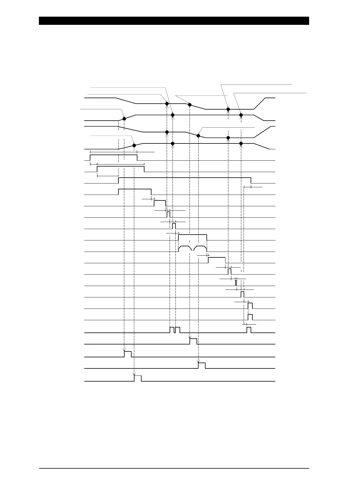
12. Timing Chart (2-axis Type)
12-3
When 0=Setup parameter of the function menu is set as follows:
1 Disp Measure Mode setting: SYNC(0)
2 LS Input Validity setting: Invalid(1)
3 Self Hold Validity setting: Valid(0)
18ms
2ms
2ms
2ms
1ms3ms
3ms
2ms
2ms
5ms
2ms
1ms
2ms
1ms
3ms
20ms min.
20ms min.
Before Weld Force measurement position
After Weld Work measurement position
After Weld Force measurement position
Before Weld Work measurement position
Displacement measurement
After Weld Force measurement
After Weld Work measurement
Before Weld Force measurement
Before Weld Work measurement
SV11 to 13,21 to 23 output
LEV-DISP11 to 13 output
LEV-FORCE11 to 13 output
LEV-DISP21 to 23 output
LEV-FORCE21 to 23 output
(Weld Start output)
ST-DISP1 input
ST-DISP2 input
GOOD output(*5)
FINISH output(*5)
NG output(*5)
(*1)
(*3)
(*3)
(*7)
(*7)
(*7)
(*7)
(*6)
(*1)
(*2)
(*4)
Hold-Time(setting)
Weld-Time(setting)
Squeeze-Time(setting)
Vibration check
Welding(power supply)
LEV-DISP1 set displacement
LEV-FORCE1 set force
LEV-DISP2 set displacement
LEV-FORCE2 set force
Displacement change 1
Force change 1
Force change 2
Displacement change 2
20ms max.
*1 When Self Hold Validity is set to Invalid(1), hold the ST-DISP input until the
sequence moves to Weld-Time.
*2 Varies depending on the allowable vibration range setting and vibration stability
time.
*3 The output time of Before/After Weld Time varies depending on settings of Force
Sampling and Force Average.
*4 Set the time longer than the total weld time of welding machine for Weld-Time.
 Loading...