CHAPTER 1: DESCRIPTION
UB25 LINEAR DC RESISTANCE WELDING CONTROL
990-665 1-11
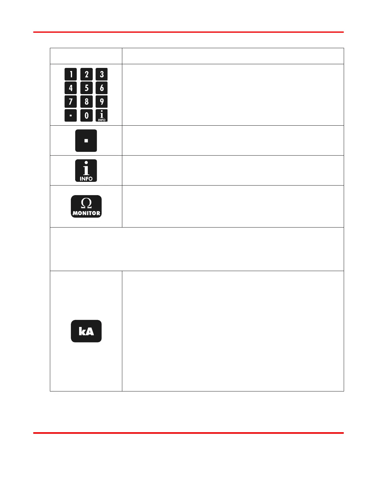
KEY FUNCTION
Numeric Keypad
Enter or modify weld period time and energy values.
Enter or modify monitor and limit values.
Directly recall a specific weld schedule.
Select menu items when MENU screens are displayed.
Press to insert a decimal point into the time and energy values you enter.
Press to display the version number of the Power Supply software and
other pertinent information about the Power Supply.
When in the MONITOR state, press to view the resistance waveform of
the last weld. The resistance waveform and values are provided as a
reference and are designed to provide an illustration of the resistance
change during the weld.
NOTE: The kA, V, and kW keys are used to:
• Set the feedback mode for Pulse 1 and Pulse 2 in the weld schedule.
• Set the feedback parameters for upper and lower monitor limits.
• Select the monitor mode to be viewed on the LCD display.
When PROGRAM is displayed, this key is used to set current as the
feedback mode for Pulse 1 or Pulse 2. First, use the WELD key to
highlight the energy field, then enter the desired output level with the
numeric keypad, then press the kA key to change the feedback mode to
current.
When MONITOR or RUN is displayed in the MONITOR state, this key
is used to set current as the limit parameter for Pulse 1 or Pulse 2. First,
use the WELD key to highlight the energy field, then enter the desired
limit level with the numeric keypad, and then press the kA key to change
the limit parameter to current.
When MONITOR or RUN is displayed in the MONITOR state, press
the kA key to view the current graph on the LCD display.