PN 903-8797, Rev A
Primary
Code
Error
Code
Alarm
Type Condition / Description / Suggested Corrective Action
256 9 Fault f H2O Dim [Light-Intensity-On-Water-Side-Is-Too-Low]
512 10 Fault f HC Dim [Light-Intensity-On-Hydrocarbon-Side-Is-Too-Low]
These alarms indicate problems with the LED/photo detector Opto-Ring (inside the
Measuring Cell).
Corrective Action:
While referring to the procedures under “Measuring Cell Maintenance” in this chapter,
take all appropriate precautions to ensure the area is safe and then:
Note:
The gas must be turned o at the Sample/Vent valves and the sample system pressure
must be bled down before performing any maintenance.
• Clean the Measuring Cell, including the optic-path windows.
• Check the LEDs inside the Measuring Cell.
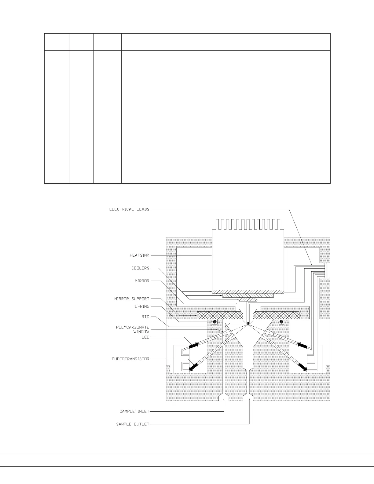
Refer to Figures 4-1 and 4-5 for locations of internal components. With the Measuring
Cell removed, observe the Opto-Ring to check if both LEDs are on.
If necessary, contact AMETEK Service for assistance.
Figure 4-5.
Measuring Cell Assembly,
cutaway view.
4-54 | 241CE II Hydrocarbon Dewpoint Analyzer

 Loading...


