PN 903-8797, Rev A
Analog Input Terminals
An external water signal (a 4–20 mA input) can be brought in to the analyzer
and then displayed as water dewpoint temperature (WDP) or water content
(WCT) on the User Interface or designated V/I outputs.
To congure the analyzer to accept an external water signal and display it on
its User Interface, additional equipment must be installed on the Microcon-
troller and Termination boards (typically done at the factory). Certain analyz-
er parameters must also be calibrated to adjust input ranges. See AppendixA
for additional information.
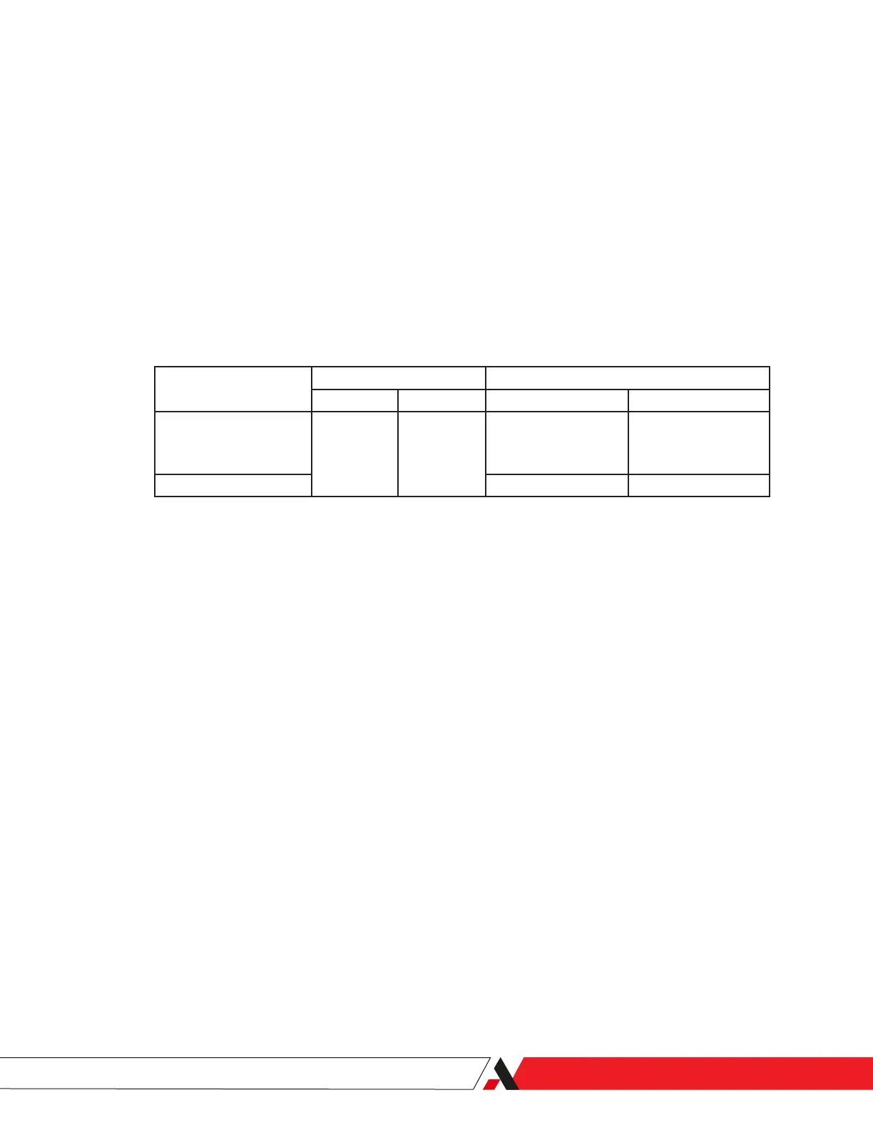
The units of measurement (except the Remote Start option – xed input) can
be changed from Metric to Imperial (Figure 2-4).
Analog Input Signal
Terminal Units
+ – Metric Imperial
* External Water Signal
(either WDP or WCT)
J101 12 J101 13
°C (WDP);
mg/m
3
(WCT); PPMV;
PPMW (WCT)
°F (WDP);
lb/MMcf (WCT); PPMV;
PPMW (WCT)
Remote Start N/A N/A
* These signals are optional; only one of these signals can be enabled at any time.
N/A = Not applicable.
Figure 2-4.
Analog inputs, terminals,
and units.
Installation and Start-Up | 2-19

 Loading...


