3-7
3.1 Panel Arrangement
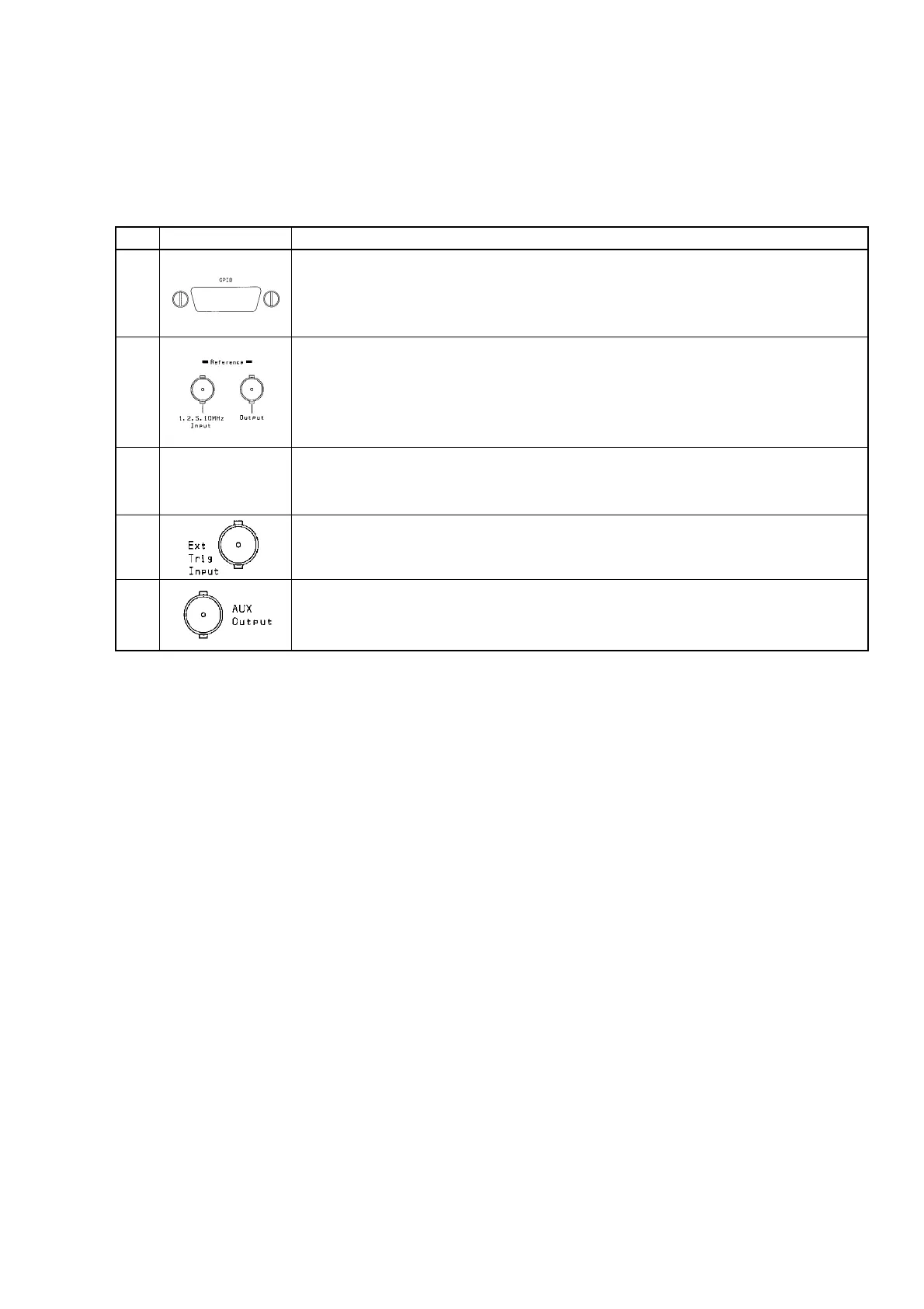
Table 3-3 Function of Back Panel Components (Continued)
No
5
6
7
8
9
Label
GPIB Interface Connector
If you want to control the unit from a host computer, connect a GPIB cable here and
attach the other end to the host computer.
Make sure you turn the unit and host computer power off before connecting this cable.
Reference Signal Input Connector and Reference Signal Output Connector
When operating the unit using an external reference signal, input the signal to the
reference input connector. The unit is ready for four frequencies: 1, 2, 5, and 10 MHz.
The reference signal used by the unit is output from the reference signal output
connector.
Fan
Fan that lets out hot air from inside the unit. The fan must be at least 10 cm away from
any surrounding obstacles.
Ext Trig Input Connector
Input connector for timing frequency measurement with an external device.
This input is active when you set Ext Trig to be used.
AUX Output Connector
Connector for outputting signals from unit components. It outputs the signal selected
by a parameter setting.
Description