Section 3 Panel Arrangement and Operation Overview
3-6
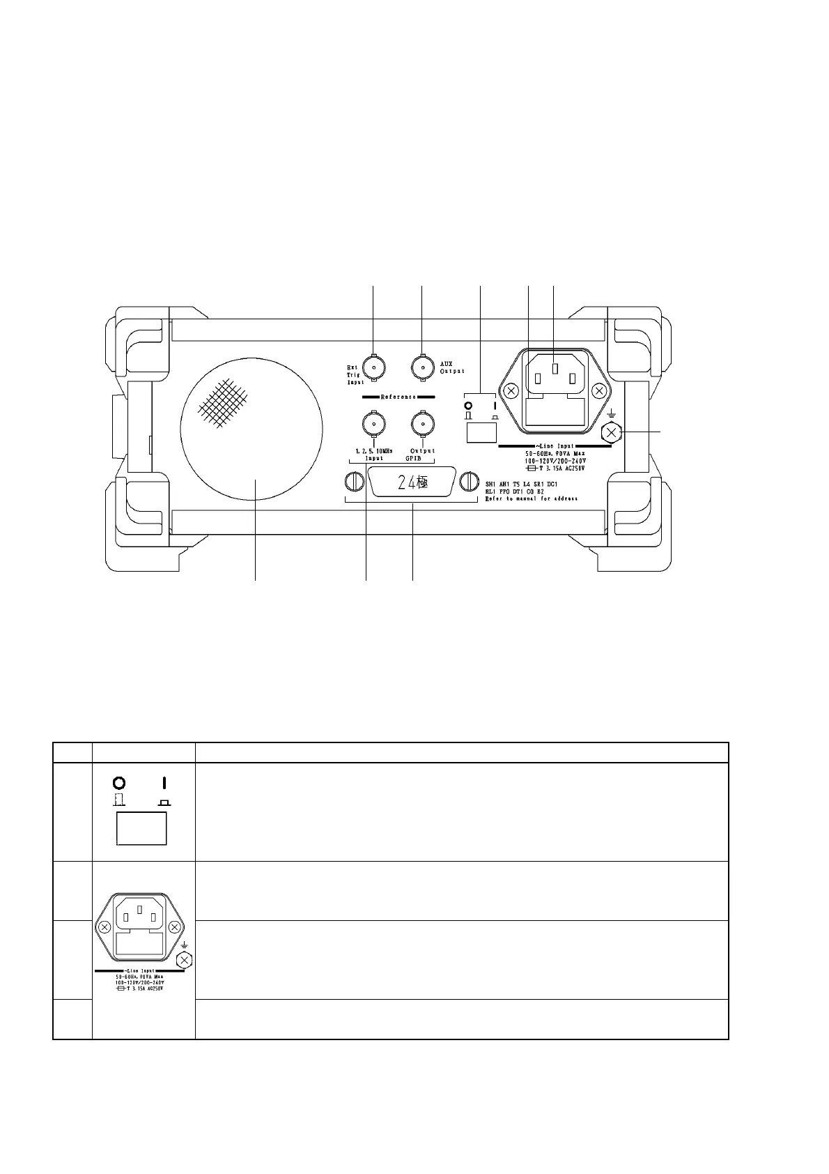
3.1.3 Back Panel
Fig. 3-3 shows the unit’s back panel and Table 3-3 describes the functions of its components.
8 9
1 32
7 6 5
4
Fig. 3-3 Diagram of Back Panel
Table 3-3 Function of Back Panel Components
No
1
2
3
4
Label
Power Line Switch
Switch for supplying power to the unit.
Moving the power switch from the Off to the On position (switch is pressed down) openly
supplies power to the crystal oscillator. Turning on the power button on the front panel at
this time will supply power to the various components on this unit.
Fuse Holder
Contains a fuse. When replacing a fuse, make sure to use one of the same type and rating
to avoid injury and damage to the unit.
AC Power Inlet
Connect the power cord here.
Make sure to use only a cord properly rated for this unit to avoid injury and damage to the
unit.
Functional earth terminal
This is the terminal that is electrically connected to the chassis of the equipment.
Description