3-5
3.1 Panel Arrangement
3.1.2 Side Panel
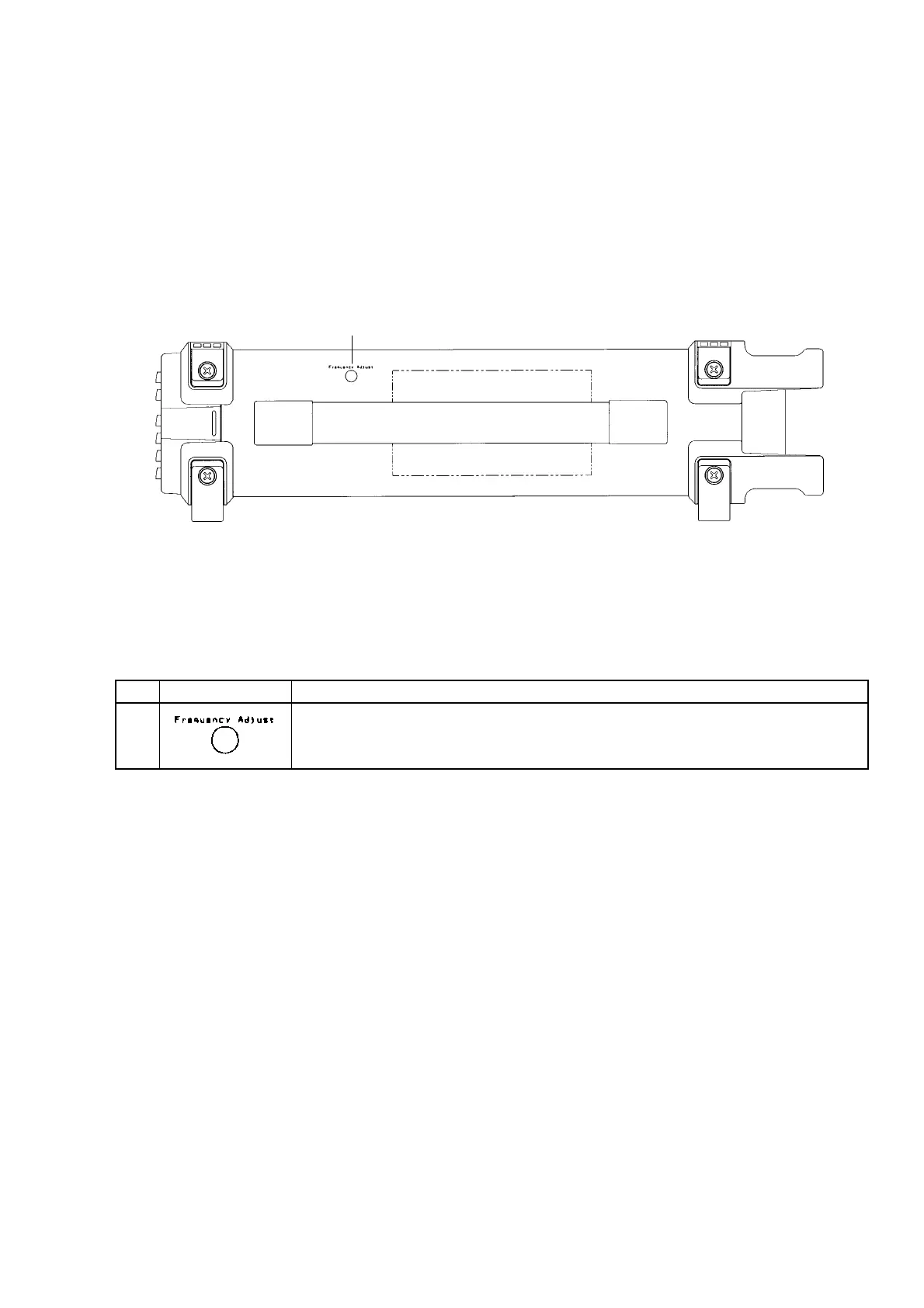
Fig. 3-2 shows the unit’s side panel and Table 3-2 describes the functions of its components.
1
Fig. 3-2 Diagram of Side Panel
Table 3-2 Function of Side Panel Components
No
1
Label
Internal Reference Signal (10 MHz) Adjustment Hole
Adjust the frequency of the reference crystal oscillator following the procedure
described in Section 8, “Calibration.”
Description