Chapter 2 — Spectrum Analyzer Verification 2-8 Absolute Amplitude Accuracy Verification
MS2720T MM PN: 10580-00342 Rev. D 2-15
Equipment Required for MS2720T with option 732 or 743
• Anritsu MG3695C Synthesized Signal Source (see equipment list for required options)
• Frequency Reference Symmetricom Rubisource T&M
• Anritsu 34VKF50 50 ohm Adapter
• Anritsu 3670K50-2 K RF
• Coaxial cable, BNC(m) to BNC(m), 50 ohm
• Power Meter, Anritsu Model ML2438A
• (2) Power Sensor, Anritsu Model SC7413
• Power Splitter Anritsu Model K241C
• Fixed Attenuator, Anritsu Model 41KC-10
Component Characterization
1. Connect both power sensors to the power meter, and then zero the sensors.
2. Connect the 10 MHz Reference source to the 10 MHz Ref In connector of the MG3692x or MG3695C
Synthesized Signal Generator.
3. Connect the Model 1870A or K241C power splitter to the MG3692x or MG3695C output via the 34NN50A
or 34VKF50 adapter, and connect Sensor B to one of the power splitter output connections (refer to
Figure 2-3).
4. Install the 10 dB Fixed Attenuator to the other power splitter output, and then connect Sensor A to the
end of the Attenuator.
5. Set the frequency of the MG3692x or MG3695C to 50 MHz.
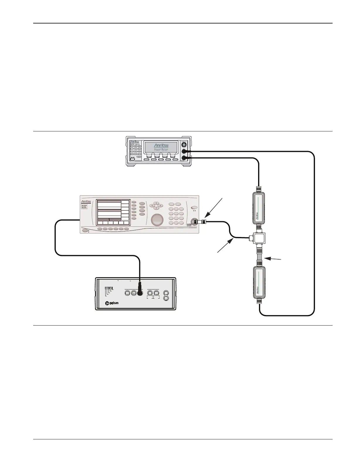
Figure 2-3. 50 MHz Amplitude Accuracy Verification for Models with K Connectors
MG3692x Signal General
ML2438A Power Meter
Sensor A
Sensor B
K241C
Power Splitter
41KC-10
10 dB
Attenuator
Adapter
3670K50-2
10 MHz Reference
Oscillator Warmup
Oscillator Ready
Failure
1 PPS Sync
1 PPS OUT
1 MH z 5 MH z 1 0 MH
5 MHz 10 MHz
Sine wave Out AUX
1 PPS IN
Power
TESTIME
PLUS
R
RubiSource T&M
R
Ext Ref In
(back panel)
10 MHz
Sine Out
 Loading...


