EN – 13
Generation 2 Chute Control Design
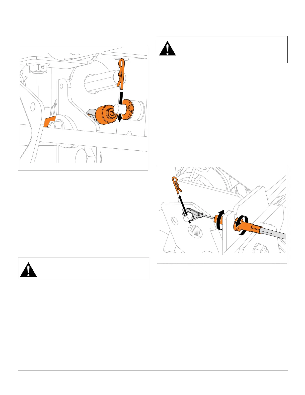
23. Remove hairpin from chute control assembly and
reinstall cable eyelet onto assembly. Reinstall hairpin.
See Figure 18.
All Models
24. Reinstall gear cover and secure with tapping screw.
25. Reinstall chute deflector cable into J-clamp on engine
mount.
26. Reinstall deflector cable anchor into deflector bracket.
27. Remove sleeve bushing and hairpin from deflector
arm and reinstall cable eyelet onto deflector arm.
Reinstall sleeve bushing and hairpin. See
Figure 7.Reconnect spark plug wire.
28. Adjust chute lock cable and deflector cable. Refer to
operator’s manual for instructions.
IMPORTANT: Check all adjustments after first use.
BOTTOM COVER REMOVAL
IMPORTANT: Save all hardware for reinstallation.
1. Stop engine, remove key and wait for all moving parts
to stop and for hot parts to cool.
2. Disconnect spark plug wire from engine.
3. Place unit in service position. See Service Position on
page 7.
4. Models 921045, 921046, 921047, 921048, 921049,
921323, 921324: Advance to step 10.
Models 921326, 921328
5. Rotate track to the raised position. Refer to operator’s
manual.
See Figure 19.
6. Remove hairpin and cable eyelet from lock finger.
7. Loosen cable adjustment barrel nuts and remove
cable from height-adjuster bracket.
WARNING: AVOID INJURY. Auger / impeller
must stop within 5 seconds when attachment
clutch lever is released.
Figure 18
Generation 2 Chute Control Design
WARNING: AVOID INJURY. Before placing unit
in service position, drain fuel from tank and fuel
system. See Draining Fuel System on page 7.
Make sure unit is secure and will not tip.