EasyManuals Logo

Array electronic SH-300 User Manual

Array electronic SH-300
103 pages
To Next Page IconTo Next Page
To Previous Page IconTo Previous Page
Page #91 background imageLoading...
Page #91 background image
SH-300
User’s Manual Connection with PLC
Page 91 of 103
When reading coil M25 status the data format of query message from SH-300 and response
message from controller is shown as following:
Byte
NO.
Query format (controller receive)
Example
Response format (controller
send)
Example
0
Framing starting
55
Framing starting
55
1
Framing starting
55
Framing starting
55
2
Device address
01
Response status
FF
3
Function code
40
Device address
01
4
Address offset
00
The function code
40
5
Reserved byte
00
Addressing offset
00
6
Reserved byte
00
Reserved byte
00
7
Address high order bit (Hi byte)
00
Reserved byte
00
8
Address high order bit (Lo byte)
00
Address high order bit (Hi byte)
00
9
Address Low order bit (Hi byte)
00
Address high order bit (Lo byte)
00
10
Address Low order bit (Lo byte)
19
Address Low order bit (Hi byte)
00
11
Reserved byte
00
Address Low order bit (Lo byte)
19
12
Reserved byte
00
The status message of one coil
01/00
13
Reserved byte
00
Reserved byte
00
14
Reserved byte
00
Reserved byte
00
15
Reserved byte
00
Reserved byte
00
16
Verify value
04
Verify value
04/03
Description :
The value of Register and coil address is stored as byte value. According to the value of the
address first use address Low order bit, and then use address high order bit. For each address
bit , The first byte contains the high order bits and the second byte contains the low order bits.
The framing of query and response message contains seventeen bytes which is fixed .
Framing starting [55][55] :the value is fixed.
Addressing offset [00]: If coils M0 is addressed as 0 the address offset is [00], If coils M1 is
addressed as 0 the address offset is [01],
Response status: 0x00 expresses error ,0xFF expresses right
Address low order bit: [00][19] expresses that the address of the coil to be read is 25 (D).
The response state [FF] expresses normal response, [00] expresses abnormal response.
Verify value: plus all bytes from framing starting byte to the penultimate byte, take the last byte of
the summation as verify value.
2. Write Single Coil M (0x41)
Use this function code to setup ON/OFF state of single coil in controller
The ON/OFF state of requested coil is specified by a constant in the query data field. A value of
FF 00 hex requests the coil to be ON. A value of 00 00 requests it to be OFF. Any other values
are illegal and will not affect the coil.
Here is an example of writing coil M25
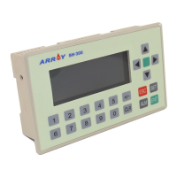
use function key to set the coil status and use indicator to indicate it.

Questions and Answers:

Question and Answer IconNeed help?

Do you have a question about the Array electronic SH-300 and is the answer not in the manual?

Array electronic SH-300 Specifications

General IconGeneral
BrandArray electronic
ModelSH-300
CategoryController
LanguageEnglish

Related product manuals