Optics 143
Remove the blinding plate from the camera by loosening its 2x 3mm
allen screws.
Place the OVF on the camera.
Take special care that the electronic connectors of camera and
viewfinder are connected before pushing the OVF in place.
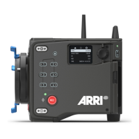
Tighten the 3x 3mm allen screws of the OVF (See OVF top view
image for locations of screws).
Note: The torx screws on the camera that are painted red may not be tightened or
loosened, as this would corrupt the alignment of the OVF.
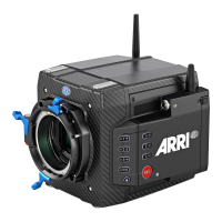
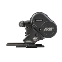
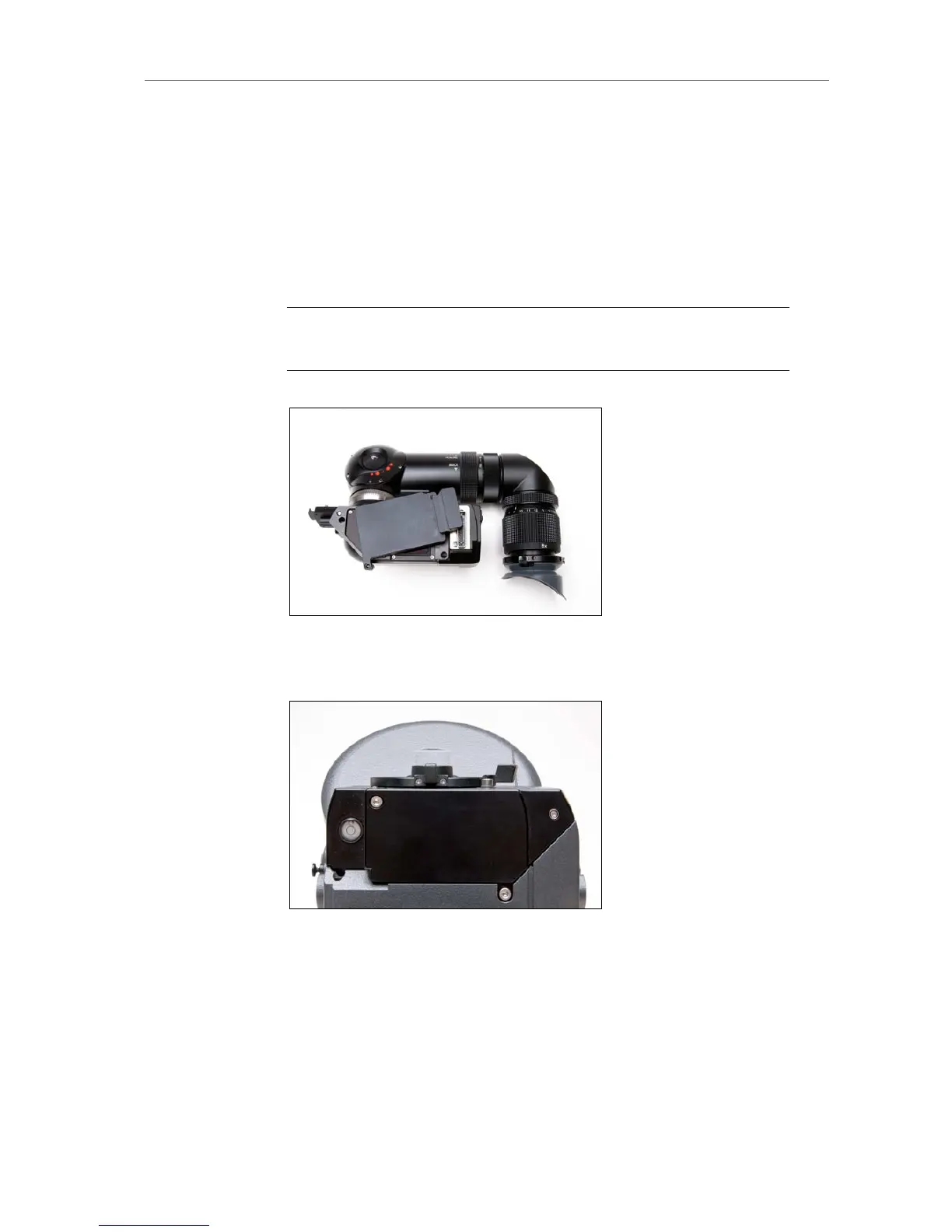
Figure 108: OVF with cover plate
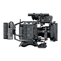
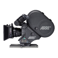
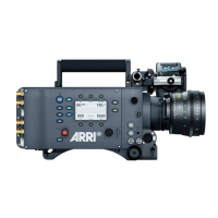
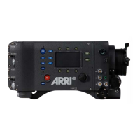
Figure 109: Alexa Studio with cover plate
Swapping the optical viewfinder for an electronic viewfinder EVF-1
Make sure the camera is powered down.
Loosen the 3x 3mm hex screws of the OVF completely (See OVF top
view image for locations of screws).