TD 92483GB
2008-06-05/ Ver. B
Installation and Operation Manual
UPAC- Unite Packet for Messaging and Alarm
96
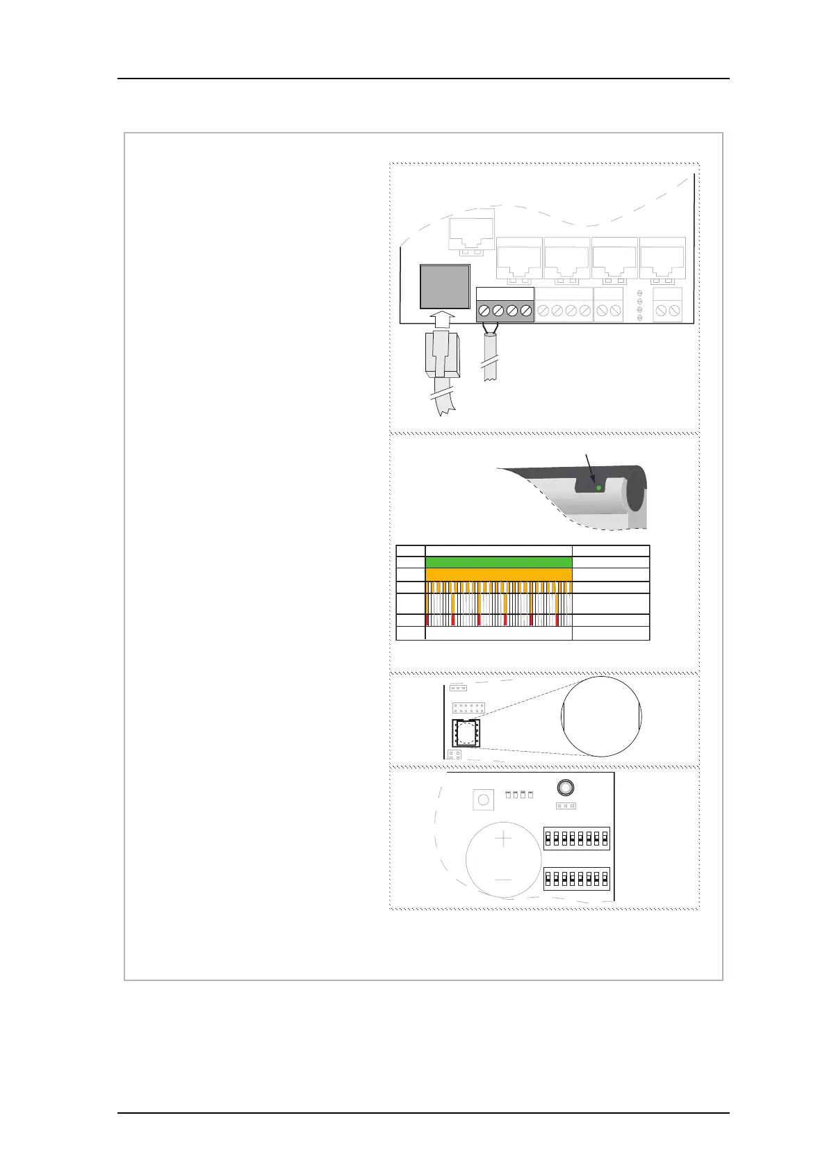
Figure 59. Getting Started leaflet (page 2 of 2)
M0276300 Ver. D, June 2008
Connections
Figure 1 shows the placement of the connectors
used for the startup of the product.
Cables
Ethernet cable:
• Use a cross-over cable if connected directly to a
PC
• Use an ordinary cable (straight through pinouts)
if connected to the LAN
Function indicator
Figure 2 shows the function indicator and different
status.
Note: If a DECT Exchange is selected in the
wizard as wireless phone system but not yet
connected, the Starting up status will be
indicated until connected.
Module key number
Figure 3 shows where to find the module key
number on IC24.
Operation switches SW2 and SW3
Figure 4 shows the placement of SW2 and SW3 and
ON/OFF positions.
J5 Connection of supply voltage.
J20 For connection of 10baseT or 100baseT
Ethernet TCP/IP network.
J13
J12
J11
J8
J7
J24
J14J6J5
J20
RS232:3
ETH
900 900RS232:2
S4
S5
S1
S2
2
21
1414 1
Supply voltage in
LAN or PC
RS232:1
Figure 1
+12V GND
Status
Colour
Green
Orange
OK. Running
Network setup mode
LED Indication
Orange
Orange
Red
Starting up
1
Power up
Restart
Licence error
Each segment = 100 ms
Figure 2
Function Indicator
1
Starting up mode is indicated during start of applications or if an application has lost
connection to a required resource, for example DECT Exchange
J4
IC24
J22
Figure 3
0123
4567
0123
4567
BAT1
SW4
LED
LED1
J1
SW2
SW3
1
8
2 3 4 5
Figure 4
ON
OFF
ON
OFF
1
8