EFD1000 Installation Manual
DOCUMENT # A-01-126-00 PAGE 136-225 Revision H
© Copyright 2009 Aspen Avionics Inc.
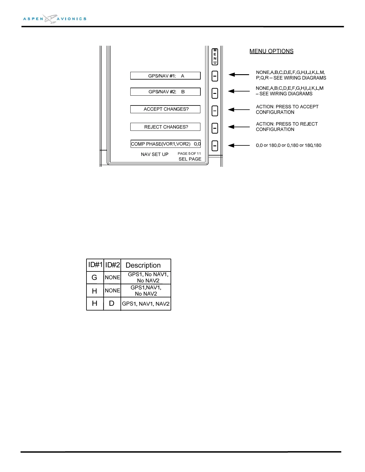
Figure 10.15 – Installation Menu Page 5
GPS/NAV#1 (ID#1): Ranges from A to R as specified on the wiring diagrams of Section
9. See example below
GPS/NAV#2 (ID#2): Ranges from A to M as specified on the wiring diagrams of Section
9. See example below.
Using the Configuration Table from Figure 9.11 as an example;
If you wired the drawing exactly as shown you would select ID#1 = H and ID#2 = D.
This would mean you have a RS-232/Analog GPS1 (i.e., KLN-94, GX-55) with an
Analog NAV1 (i.e., KX-155A) and an Analog NAV2 (i.e., KX-155A).
If you have the above installation without a NAV2 then select ID#1 = H and ID#2 =
NONE.
If you have the above installation with no NAV1 or NAV2 (just GPS and autopilot) then
select ID#1 = G and ID#2 = NONE.
 Loading...


