EFD1000 Installation Manual
DOCUMENT # A-01-126-00 PAGE 53-225 Revision H
© Copyright 2009 Aspen Avionics Inc.
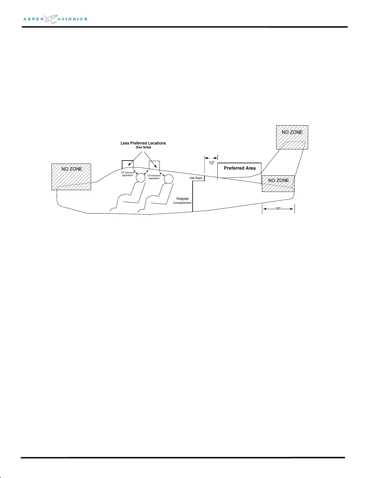
stabilizer, the horizontal stabilizer, the fuselage forward of the cabin, or within 39” as
measured from the fuselage aft end as shown.
The RSM should not be mounted within 18 inches of a VHF Comm antenna, 6 inches of a GPS
or ELT antenna, and within 2 inches of another RSM.
The RSM will need to be mounted to a relatively flat surface such that there is less than .030”
gap surrounding the RSM when installed. The RSM must not be mounted to an excessively
curved area which could become deformed upon mounting the RSM.
Figure 6.7 - RSM Mounting Location
6.9.1 Proposed RSM Location Check
The installer must determine the best RSM location given the above factors. A
navigation quality handheld compass (i.e., hiking compass) can be used to find a
magnetically quiet area free from the effects of magnetic disturbances from flight
controls, autopilot servos, strobes, or any other large magnetic field appliance.
The RSM can detect magnetic fields in three dimensions. This means that magnetic
influences below the RSM can also affect performance. Be sure to evaluate potential
magnetic influences below the RSM.
NOTE: Changes to the magnetic field around the RSM can affect the RSM
calibration and require revalidation of the RSM performance.
Known sources of interference include (but are not limited to) the following types of
material located near the RSM (normally, these materials within 12 inches can cause
interference):
a. Steel-wound hose (e.g. SCAT
tube)
d. Servos
e. Trim motors
b. Steel hose clamps f. Poor bonding of electrical
connections c. Magnetized or magnetic
hardware g. Blower motors