EFD1000 Installation Manual
DOCUMENT # A-01-126-00 PAGE 34-225 Revision H
© Copyright 2009 Aspen Avionics Inc.
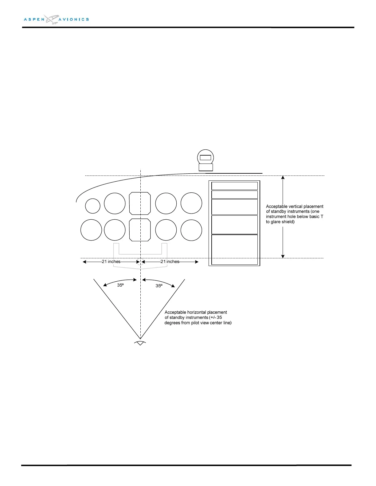
5.2.1 Standby Attitude Positioning
The Attitude indicator must be relocated to a position that meets FAR 23.1321(a). The
requirements are ±35 degrees from the pilot’s center line horizontally (± 21 inches
from centerline as defined by AC23-11) to an area just below the basic T configuration
to the glare shield vertically (see Figure 5.2 below). Standby instruments should be
mounted as close as practical to the primary instruments, but in no case outside ±35º.
NOTE: The existing instrument hole for the Vertical Speed indicator is one location
that meets this requirement.
Figure 5.2 – Standby Instrument Placement
Also note that some attitude indicators (i.e., KI-256) are the primary pitch and roll
reference for the autopilot and must remain in the aircraft but may be co-pilot or blind
mounted provided a standby attitude indicator is located within the pilot’s field of
view. For rate based autopilots the Turn and Bank Indicator will need to remain in the
aircraft, and may be relocated to the co-pilot side or blind mounted provided it is not
used as the autopilot mode controller. If used as the autopilot mode controller then it
must be located where it can be easily reached by the pilot while seated.