EFD1000 Installation Manual
DOCUMENT # A-01-126-00 PAGE 47-225 Revision H
© Copyright 2009 Aspen Avionics Inc.
6.8 PFD Installation
Mechanical installation of the PFD requires installing the included mounting bracket,
connecting a braided bonding strap between the PFD and panel, and installing pitot and static
connections to the two keyed quick release pressure fittings.
NOTE:
To avoid damage to the equipment, do not place the EFD1000 Display face down
on the knobs
.
6.8.1 Connecting the Internal Battery
The internal battery is normally disconnected for shipping and must be reconnected prior to
the Post Installation Flight Check and maintenance release of the aircraft.
Connection of the battery is performed as follows:
1. Remove the two screws that hold the battery cover in place. The battery cover is
located below the 44 pin connector on the PFD cylinder.
2. Remove the battery cover.
3. Plug the battery connector into the mating connector within the battery compartment.
4. Re-install the battery cover. Be careful to avoid pinching the wires with the cover.
5. Re-install the two screws to hold the battery cover in place.
6. Verify “Bat:” status on page 6 of the Main Menu shows “Charging” when external
power is supplied to the EFD1000.
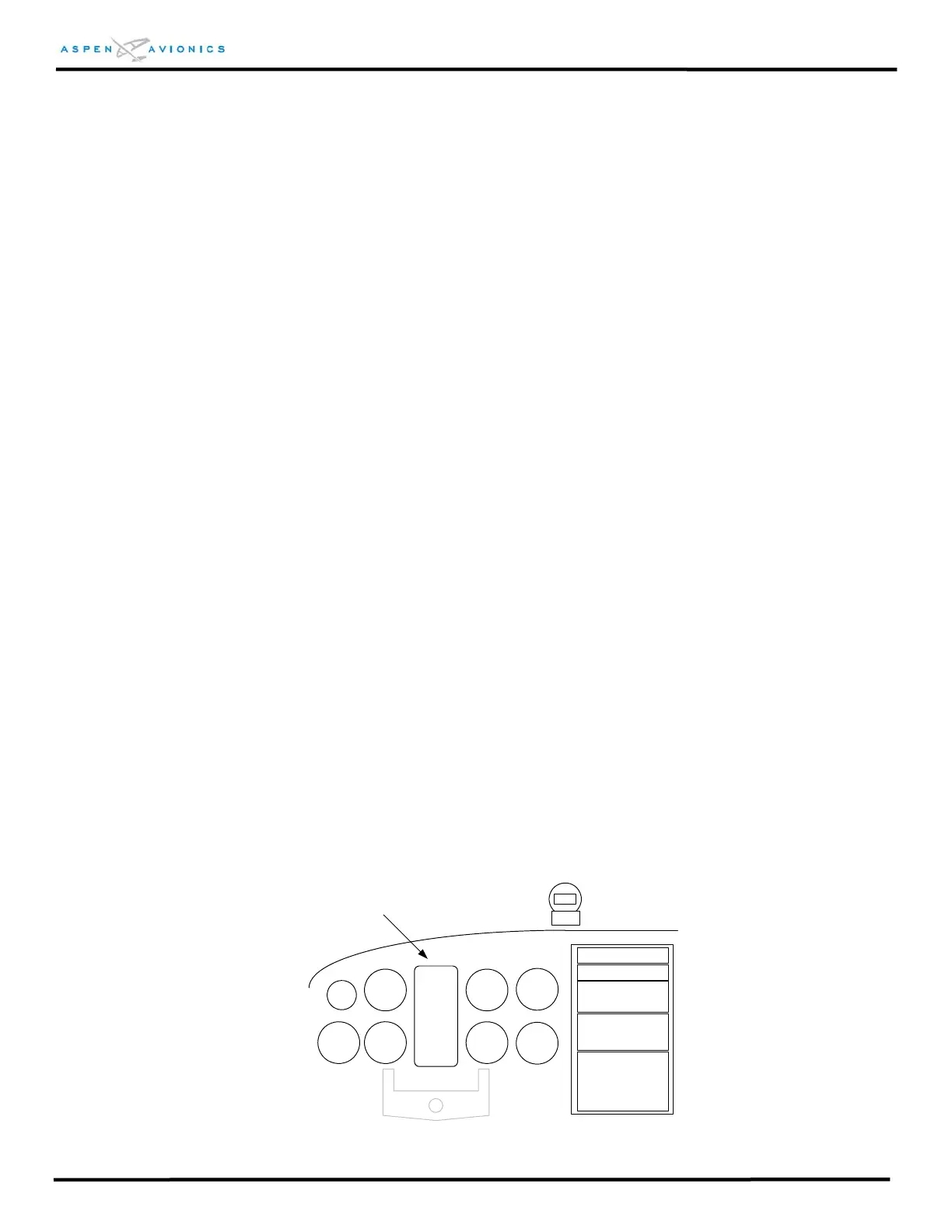
6.8.2 PFD Mounting Location
The PFD must be mounted in the center position of the instrument panel per FAR
23.1321(d). If the two existing instrument holes that contain the attitude indicator and
direction indicator are not exactly centered, but are the closest instruments to the
center, then that position is acceptable for mounting the PFD.
NOTE: Modification to the existing instrument panel is not authorized
under this STC. Any modification must be approved separately.
PFD
PFD Mounting Location
Figure 6.1 - PFD Mounting Location