EFD1000 Installation Manual
DOCUMENT # A-01-126-00 PAGE 70-225 Revision H
© Copyright 2009 Aspen Avionics Inc.
At the GPS/VLOC/ACU terminate the over braid within the back shell or as close as
possible. Ground the over braid at this end using a pigtail as short as possible. If
using double shielded wires then ground both shields at the GPS/VLOC/ACU with
pigtail as short as possible.
7.2.3 RSM Wiring
The PFD to RSM wiring run is made with a single cable seven (7) conductor shielded
wire. M27500-A24SD7T23, M27500-22TG7T14 or equivalent 22 or 24AWG seven (7)
conductor shielded cable can be used.
Assembly using Aspen P/N A-08-148-00-A 30ft cable
This cable assembly is prefabricated with the following wire color markings and will be
cut to length at the PFD.
Pin 1 White/Black
Pin 2 White/Red
Pin 3 White/Orange
Pin 4 White/Yellow
Pin 5 White/Green
Pin 6 White/Blue
Pin 7 White
Assembly using M27500-A24SD7T23 or equivalent Cable:
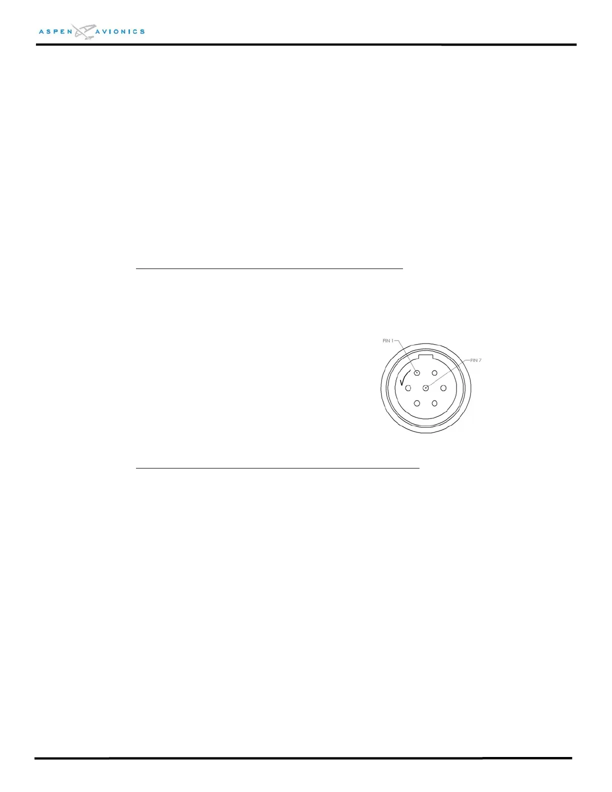
Terminate the aircraft side of the RSM wiring with the Hirose circular connector from
installation kit as shown in Figure 7.3 below. Due to the compact design of the Hirose
connector it may be easier to solder the wires to the solder cups on the bench versus
inside the tail of the aircraft. Use a fine tip soldering iron for this procedure.
1. Pass the cable through the hood and metal cover. Strip back the insulation to
expose the shielding and wires with the dimensions that are shown.
2. Stake the metal clamper to the shield in the location shown. A hexagonal crimper
such as the ones used for BNC Coax connector assembly work can be used to
crimp it to approximately 5.2mm outside diameter.
3. Assemble the two pieces of the connector such that the solder cup piece is retained
by the ring. Discard the washer as it is not required.
4. Solder the seven (7) 24 AWG wires to the connector.
5. Thread metal cover onto connector.
6. Insert screw into metal cover so that it indents into metal clamper.
7. Put hood over metal cover.