EFD1000 Installation Manual
DOCUMENT # A-01-126-00 PAGE 76-225 Revision H
© Copyright 2009 Aspen Avionics Inc.
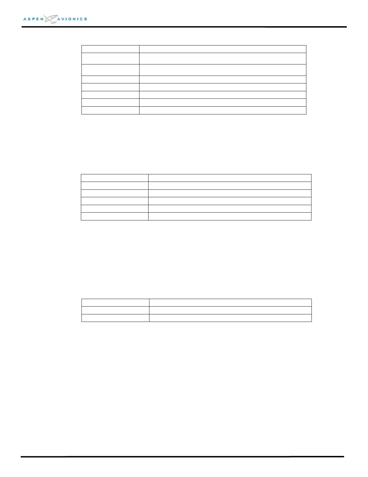
ARINC Label(s) PFD Parameter
Label 330 GPS FPL Curved “CONIC Arc Inbound Course”
Label 331 GPS FPL Curved “CONIC Arc Radius”
Label 332 GPS FPL Curved “CONIC ARC Course Change Angle”
Label 333 GPS FPL Curved “Airport Runway Azimuth
Label 334 GPS FPL Curved “Airport Runway Length
Label 335 GPS FPL Curved “Holding Pattern Azimuth”
Label 340 GPS FPL Curved “Procedure Turn Azimuth”
8.1.5 ARINC 429 VLOC Input
The PFD receives the following labels on Pins (18, 19) and (22, 23) when transmitted
from a VLOC receiver.
Input Data (Label) Name
Label 34 Tuned Frequency
Label 34, bit 14 set ILS Energize
Label 173 Localizer deviation and validity flags
Label 174 Glide Slope deviation and validity flags
Label 222 VOR Omni bearing
8.1.6 ARINC 429 GPS Output
The PFD transmits the following labels on pins 26 and 27 for GPS receivers and
systems that require low speed ARINC 429 Magnetic Heading. Note - if an ACU is
installed then the connections for the GPS and Heading will be made at
ACU P3 pins 4 and 5.
ARINC Label PFD Data
Label 100 Selected Course
Label 320 Magnetic Heading
8.2 ACU Electrical Specifications
8.2.1 Power Input
Nominal Input: 14Vdc or 28Vdc
Operating Range: 11Vdc to 32Vdc
8.2.2 Decision Height (DH) Input – PFD software version 1.1 or later
A differential input from the DH output of a radar altimeter.
DH on: Difference between +DH and –DH greater than 5Vdc
DH off: Difference between +DH and –DH less than 1Vdc
Load: 10000 ohms +DH to -DH