EFD1000 Installation Manual
DOCUMENT # A-01-126-00 PAGE 52-225 Revision H
© Copyright 2009 Aspen Avionics Inc.
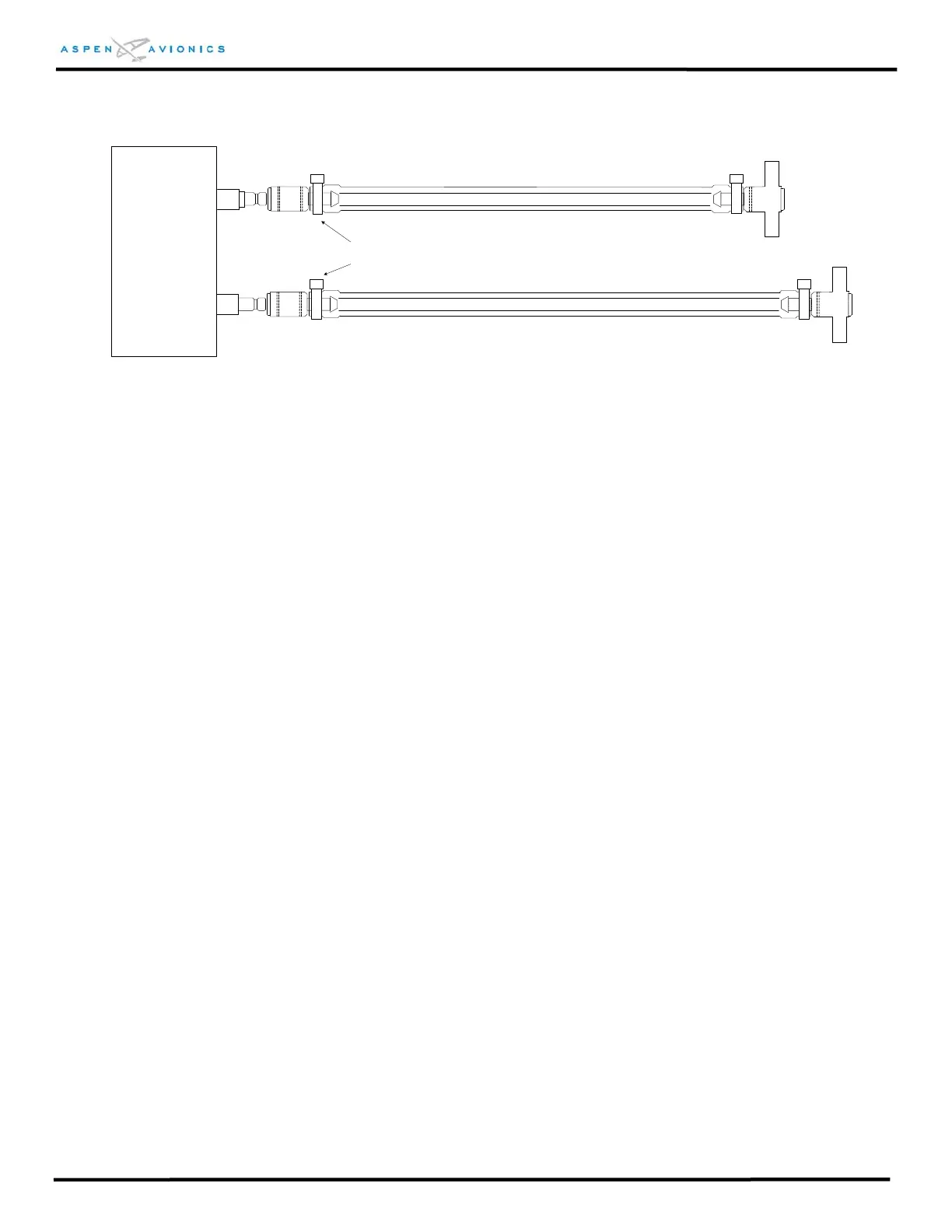
STATIC
PITOT
STATIC QUICK
CONNECTOR
A-06-505-00
PITOT QUICK
CONNECTOR
A-06-507-00
(KEYED)
EFD1000
¼” ID TUBING
PITOT
STATIC
“T” FITTING SPLICE INTO PITOT LINE
“T” FITTING SPLICE INTO STATIC LINE
HOSE CLAMP
(4 PLACES)
¼” ID TUBING
Figure 6.6 – Pitot & Static Line Connections
6.8.7 Leak Check Requirements
A pitot static leak check is required after the installation of the quick connectors and
the PFD is installed. The quick connectors are designed such that they seal when
disconnected.
6.9 RSM Installation
CAUTION: The RSM is an integral part of the attitude function of the AHRS. A stable and
magnetically quiet location for the RSM is essential for proper AHRS operation.
CAUTION: There are special considerations for mounting the RSM on composite, fabric and
pressurized aircraft. See §§6.9.2 and 6.9.3.
The RSM is typically installed near the tail of the aircraft on an unpressurized portion of the
airframe. As the RSM incorporates both the OAT sensor and the emergency GPS antenna, it
must be mounted on the top outside of the airframe. In addition, the RSM includes the
magnetic flux sensors which is why it is important to locate the RSM as far away from the
cabin and baggage (or “hat rack”) compartment as practical.
Unlike a GPS antenna that is used for primary navigation, the backup GPS usage and inherent
sensitivity do not require a full view of the sky. Therefore, the vertical stabilizer may partially
mask the antennas view of the sky/horizon. Installation on either side of the vertical fin is
acceptable.
The preferred RSM installation area is a minimum of 12 inches behind a typical baggage or
(hat rack) compartment to no closer than 39” from the end of the fuselage (see Figure 6.7).
The “Less Preferred” areas over the cabin should only be selected if impossible to find an
acceptable location within the “Preferred” area of Figure 6.7. See Note on following page.
The NO ZONE areas below are hot zones for a lightning strike and are not to be used for
mounting the RSM. The RSM must not be mounted to the wing, the top of the vertical